Light-emitting diode tube

a technology of led tubes and fluorescent lamps, applied in the direction of electroluminescent light sources, electric lighting sources, semiconductor lamp usage, etc., can solve the problems of relatively high power consumption, led tubes cannot be directly mounted on conventional fluorescent lamp holders, and the cycle is considerably short, so as to achieve cost-effective effects

Inactive Publication Date: 2014-08-14
POESEN ELECTRONICS
View PDF3 Cites 71 Cited by
  • Summary
  • Abstract
  • Description
  • Claims
  • Application Information

AI Technical Summary

Benefits of technology

[0015]Given the first control module and the second control module for simulating the generation of tube voltage of conventional fluorescent tubes and the first switching element and the second switching element for controlling the first control module and the second control module, the LED tube of the present invention can be compatible with inductive ballasts or electronic ballasts in conventional fluorescent lamp holders and converts electrical signals from the ballast into power to be received by the lighting module. Accordingly, the LED tube of the present invention can directly replace conventional fluorescent tubes without the need of changing any part of the conventional fluorescent lamp holders, thereby delivering a replaceable and cost-effective LED tube.

Problems solved by technology

However, the conventional fluorescent tubes have life cycles considerably short and roughly lasting from 3,000 hours to 4,000 hours, and have relatively low power factors, resulting in the issue of relatively high power consumption.
Hence, LED tubes fail to be directly mounted on conventional fluorescent lamp holders.
Such necessity not only costs more time, effort and expenditure but also limits the market acceptance of LED lights.

Method used


Image

  • Light-emitting diode tube
  • Light-emitting diode tube
  • Light-emitting diode tube

Examples


Embodiment Construction

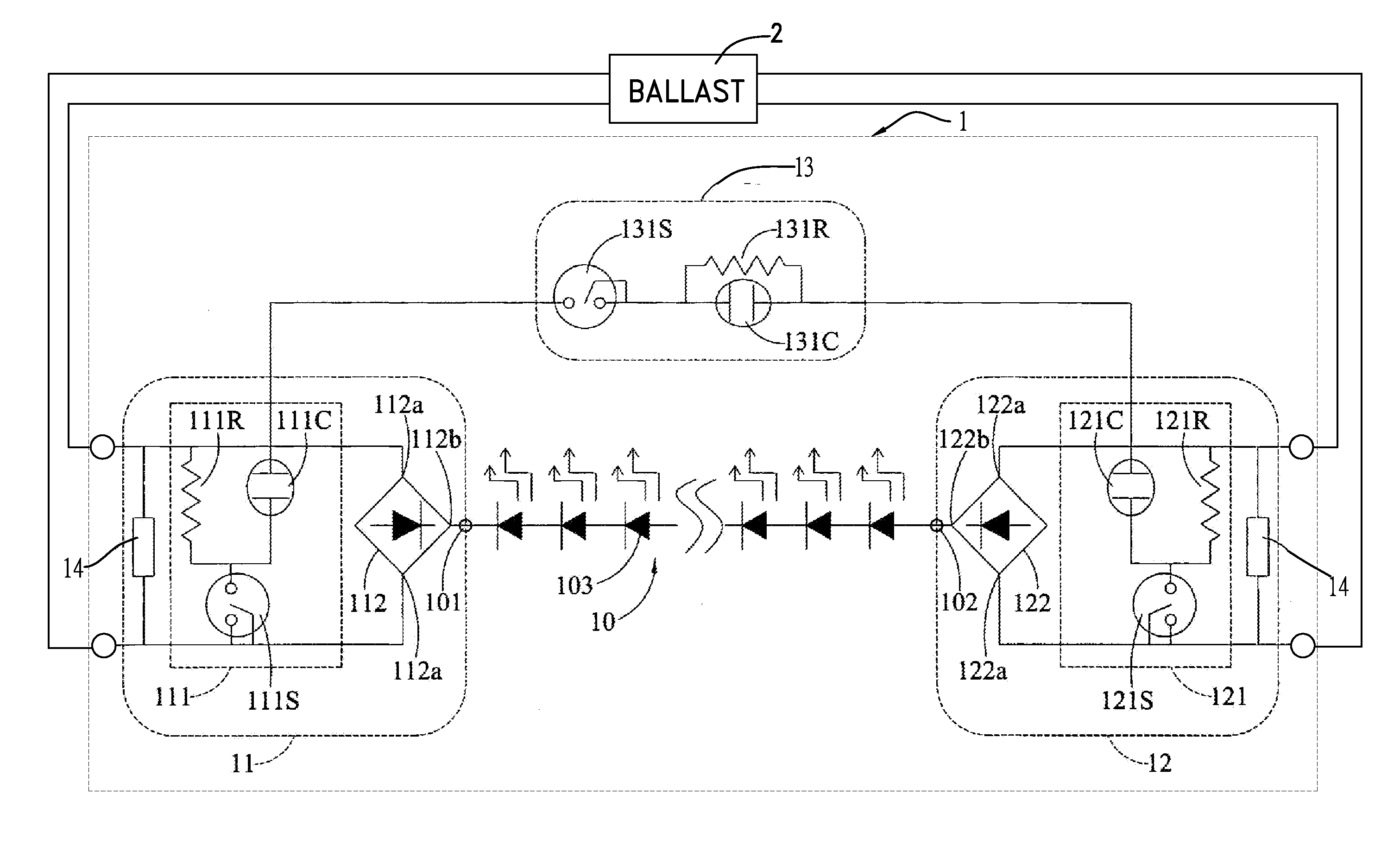
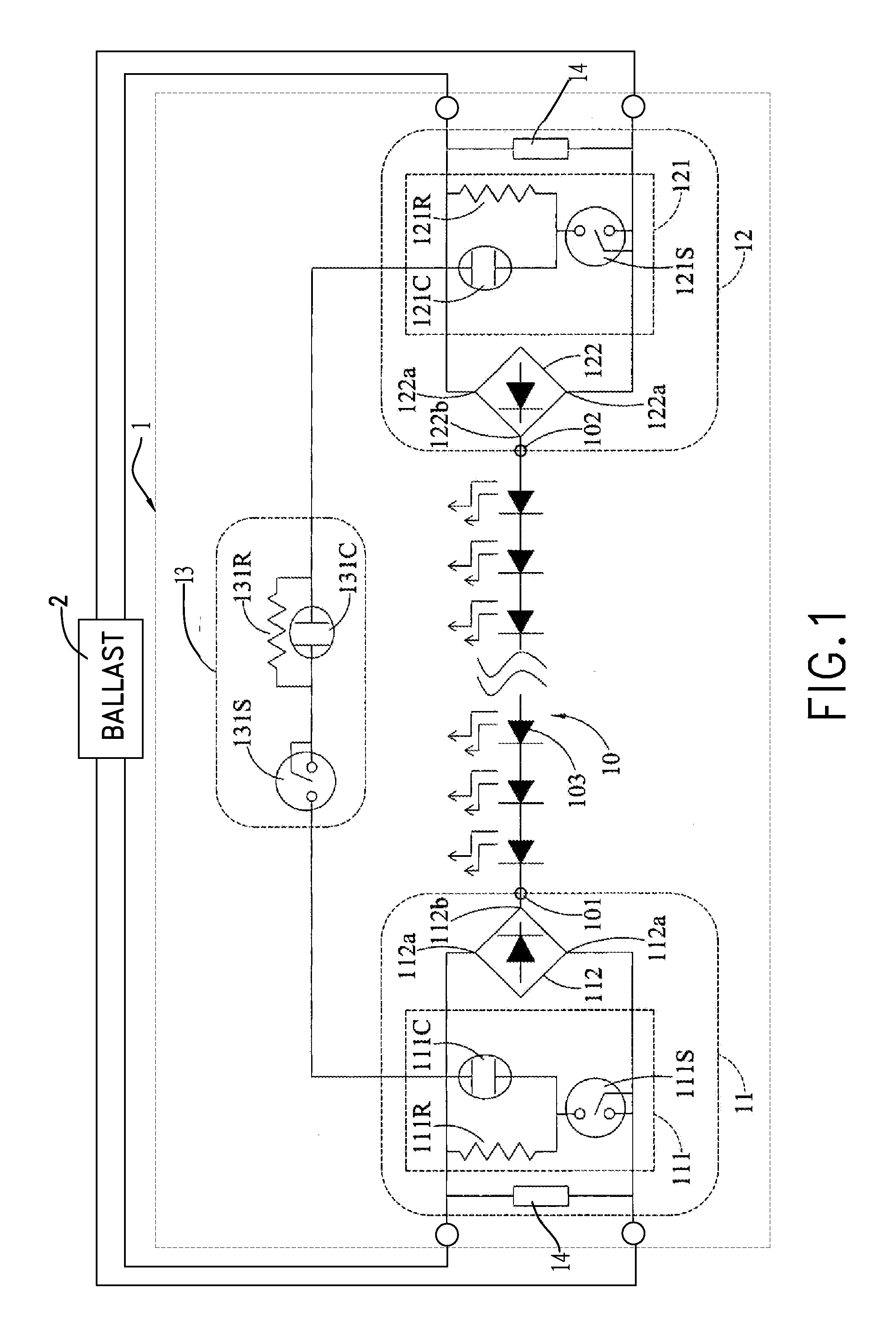
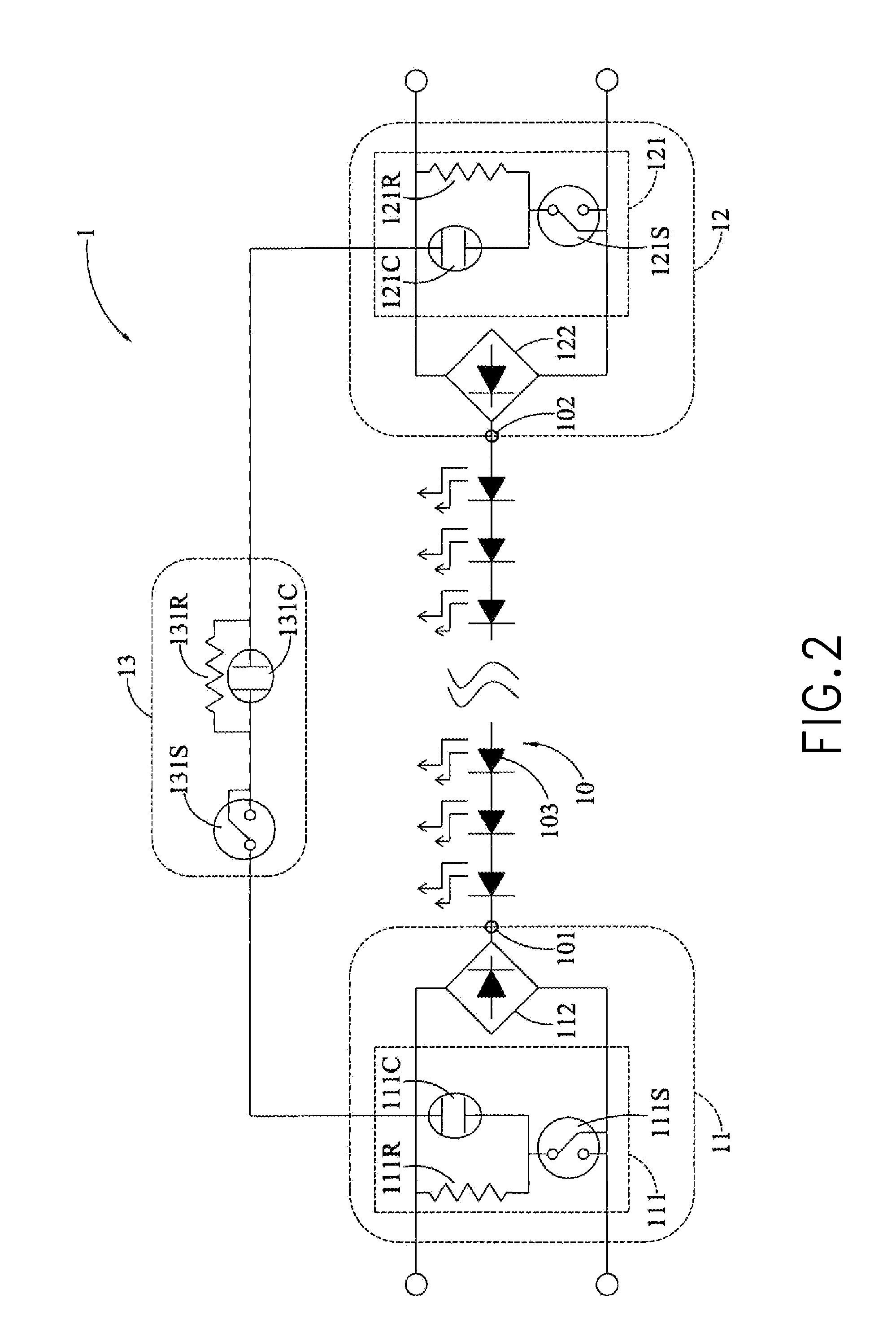
[0020]With reference to FIG. 1, a light-emitting diode (LED) tube 1 in accordance with the present invention is electrically connected to a ballast 2 of a fluorescent lamp and is lit by an operating power outputted from the ballast 2. The LED tube 1 has a lighting module 10, a first control module 11, a second control module 12 and a harmonic elimination module 13. The ballast 2 may be an electronic ballast or an inductive ballast.

[0021]The lighting module 10 has a first terminal 101, a second terminal 102 opposite to the first terminal 101, and multiple LED elements 103.

[0022]The first control module 11 is connected to the first terminal 101 of the lighting module 10, and has a first simulation circuit unit 111 and a first rectification unit 112. The first simulation circuit unit 111 has a first capacitor 111C, a first resistor 111R and a first switching element 111S. The first capacitor 111C and the first resistor 111R are parallelly connected. The first switching element 111S is ...


PUM


Abstract

A light-emitting diode (LED) tube is applied to a lamp holder with a ballast, and has a lighting module, a first control module and a second control module connected to two ends of the lighting module, and a harmonic elimination module connected to the first and second control modules and parallelly connected to the lighting module. Each of the first control module and the second control module has a simulation circuit unit and a rectification unit. Each of the simulation circuit units and the harmonic elimination module has a switching element. The first and second control modules adjust electrical signals from the ballast, and the harmonic elimination module eliminates harmonic waves generated by the ballast so that the lighting module is compatible with the ballast and is lit. Accordingly, the LED tube can be directly mounted on a fluorescent lamp holder with the lamp holder intact.

Description

BACKGROUND OF THE INVENTION[0001]1. Field of the Invention The present invention relates to a light-emitting diode (LED) tube, and more particularly to an LED tube capable of being directly mounted on a fluorescent lamp holder with a ballast.[0002]2. Description of the Related Art[0003]Fluorescent lamps have long been prevailing lighting devices, which provide uniform, stable and wide-angle lighting. Each conventional fluorescent lamp has a ballast mounted on a fluorescent lamp holder. The ballast converts an external power into a high-frequency and high-voltage power to light up a fluorescent tube and continuously supplies a stable current to the fluorescent tube after the fluorescent tube is lit. However, the conventional fluorescent tubes have life cycles considerably short and roughly lasting from 3,000 hours to 4,000 hours, and have relatively low power factors, resulting in the issue of relatively high power consumption.[0004]As a result, lighting industry and academia dedicat...

Claims


Application Information

Patent Timeline
Patent Type & Authority Applications(United States)
IPC IPC(8): H05B33/08H05B44/00
CPCH05B33/0809Y02B20/30H05B45/3725
Inventor YU, CHUNG-HUNGLIU, CHIN-TSAI
Owner POESEN ELECTRONICS
Why Eureka
Try Eureka