High efficiency power amplifier

a high-efficiency, power amplifier technology, applied in the direction of rf amplifier, amplifier with field-effect devices, amplifiers with semiconductor devices/discharge tubes, etc., can solve the problem of relativly difficult to achieve ideal states, and achieve excellent power efficiency, high efficiency power, and excellent high frequency characteristics.

Active Publication Date: 2014-08-14
UNIVERSITY OF ELECTRO-COMMUNICATIONS
View PDF3 Cites 8 Cited by
  • Summary
  • Abstract
  • Description
  • Claims
  • Application Information

AI Technical Summary

Benefits of technology

[0017]In this way, the class-F amplifier and the inverse class-F amplifier realize very excellent power efficiency. However, in order to fully separate current and voltage in actual, the harmonic power component requires a large amplitude, namely, a transistor with the excellent high frequency characteristics is required. Also, because it is easy for the class-F amplifier and the inverse class-F amplifier to undergo the influence of circuit loss, there is a case that it is relatively difficult to realize an ideal state especially in the microwave band.
[0018]One object of the present invention is to provide a high efficiency power amplifier which can be relatively easily realized in a high frequency band containing a microwave band.

Problems solved by technology

Also, because it is easy for the class-F amplifier and the inverse class-F amplifier to undergo the influence of circuit loss, there is a case that it is relatively difficult to realize an ideal state especially in the microwave band.

Method used


Image

  • High efficiency power amplifier
  • High efficiency power amplifier
  • High efficiency power amplifier

Examples


embodiment

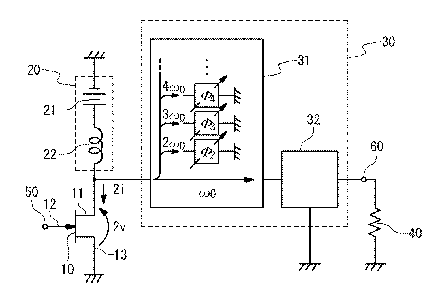
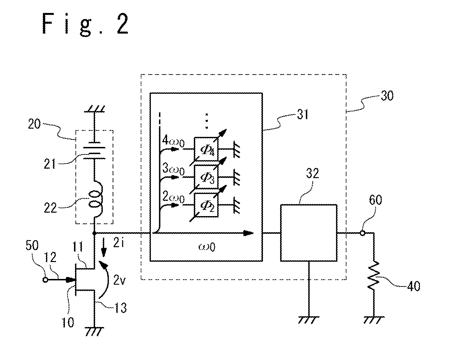
[0031]As a technique to restrain power consumption in a transistor, a reactive power control, e.g. a technique to carry out a control to reactive power by orthogonalizing a phase of current and a phase of voltage in a harmonic is thought of, in addition to a technique to zero power consumption in a transistor by separating a current flowing into the transistor and a voltage generated at the output terminal of the transistor in a time-domain, like a class-F amplifier and an inverse class-F amplifier. In the high efficiency power amplifier according to the present invention, harmonic power consumption in the transistor can be restrained by using the technique to orthogonalize the phases of current and voltage of the harmonic, independently or together with the technique to use the class-F amplifier and the inverse class-F amplifier.

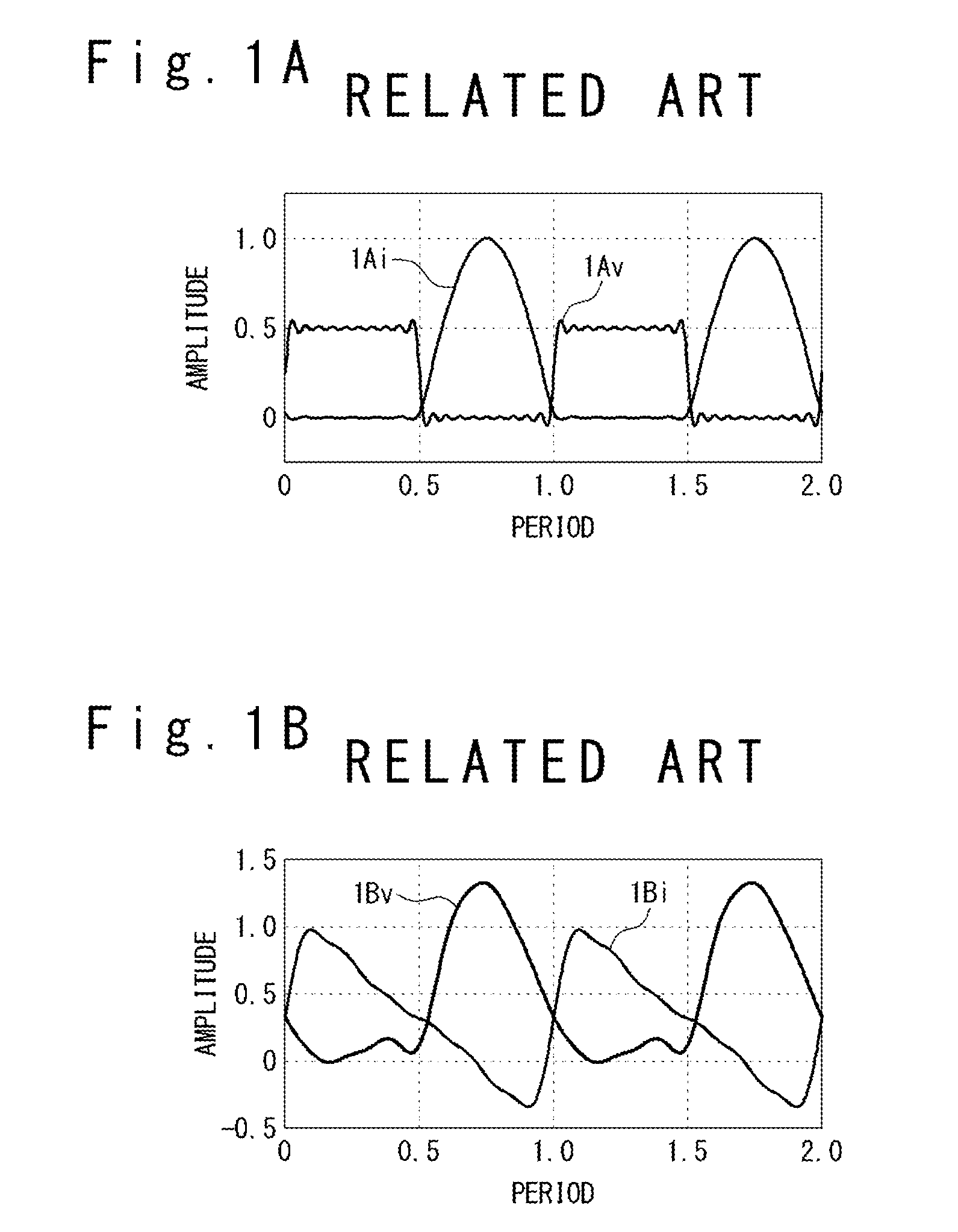
[0032]FIG. 1B is a graph group showing an example of the time change of the current flowing into the transistor and the voltage generated at the output ter...


PUM


Abstract

A high efficiency power amplifier of the present invention includes a transistor and an output power processing circuit section. The output power processing circuit section includes an output matching circuit section and an output harmonic processing circuit section. The output matching circuit section carries out impedance matching to the fundamental wave component of the output power. The output harmonic processing circuit section carries out a reactive power control to a reactive power of a plurality of harmonic power components respectively having a plurality of harmonic angular frequencies which are integral multiples of the base angular frequency of the output power. The output harmonic processing circuit section is formed to realize the reactive power control to at least one of the plurality of harmonic power components by orthogonalizing the phases of the current and voltage in the reactive power.

Description

TECHNICAL FIELD[0001]The present invention is related to a power amplifier and, especially, to a power amplifier in which power efficiency is improved by restraining average power consumption of the harmonics in the power amplifier.BACKGROUND ART[0002]In power amplification, the improvement of the power efficiency is important. When amplifying the power containing a desired fundamental wave with the power amplifier using a transistor, unnecessary power components of the harmonics of frequencies of integral multiples of the fundamental wave frequency are generated in addition to a fundamental wave power component having the fundamental wave frequency because the transistor is a non-linear device. When these unnecessary harmonic power components are consumed in the power amplifier, the power added efficiency of the power amplifier reduces.[0003]As a method of preventing the power added efficiency from reducing by controlling the harmonic power components, a method of using the class-F...

Claims


Application Information

Patent Timeline
Patent Type & Authority Applications(United States)
IPC IPC(8): H03F3/21
CPCH03F2200/387H03F3/21H03F1/56H03F3/245H03F2200/108H03F2200/255H03F2200/423H03F3/2171H03F3/601H03F1/0205H03F3/193H03F2200/222H03F2200/306H03F2200/309H03F2200/315H03F2200/391H03F2200/399H03F2200/402H03F2200/451
Inventor KAMIYAMA, MASAHIROISHIKAWA, RYOHONJO, KAZUHIKO
Owner UNIVERSITY OF ELECTRO-COMMUNICATIONS
Why Eureka
Try Eureka