Drive shaft coupling mechanism

Active Publication Date: 2014-08-14
OMNI USA
View PDF9 Cites 5 Cited by
  • Summary
  • Abstract
  • Description
  • Claims
  • Application Information

AI Technical Summary

Benefits of technology

This patent describes a coupling device that connects two shafts. It consists of a single piece shaft hub that attaches to a motor shaft, a two-piece shaft hub that attaches to an input shaft, and an elastomeric puck that lies between the two hubs. The elastomeric puck is made of a cylindrical sleeve with four outwardly extending arms that are evenly spaced around its circumference. The first hub has two flanges that engage with the puck, while the second hub has two brackets that also engage with the puck. The technical effect of this design is to provide a reliable and flexible connection between shafts that can withstand high torque and reduce vibration and noise.

Problems solved by technology

As with other components of agricultural equipment, the couplers utilized to inter-connect the square drive shaft with the round output shaft are often subject to extreme operating conditions and environments.
Likewise, because the terrain on which agricultural irrigation systems operate is often rocky, uneven and has varying surface conditions, such couplers are subject to high torque.
One drawback to these prior art couplers is that they have significant manufacturing costs, in that each collar half must be cast or otherwise formed and machined to the specifications of the particular coupling.
Further, in order to provide a coupling that is sufficiently sturdy and rugged for the agricultural industry, the metal collar components typically require a comparatively large amount of material to form the collar sections.
Another drawback to the foregoing prior art coupling devices is that the fasteners clamping the two halves of a collar around a shaft may become loose over time, particularly under the vibrations of use, permitting the shaft to spin freely within the coupling.
Not only could this result in a loss of power, but could also result in damage to the coupling, shafts, or equipment.
Moreover, if the two halves were to completely separate, they could cause harm to nearby persons or equipment.

Method used


Image

  • Drive shaft coupling mechanism
  • Drive shaft coupling mechanism
  • Drive shaft coupling mechanism

Examples


Embodiment Construction

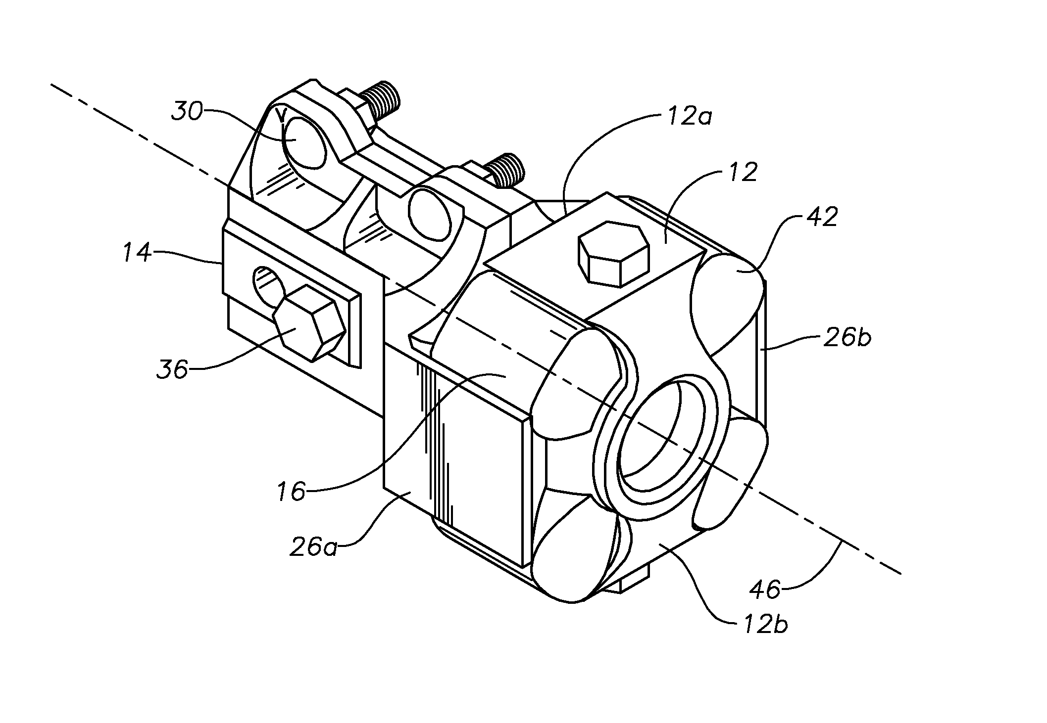
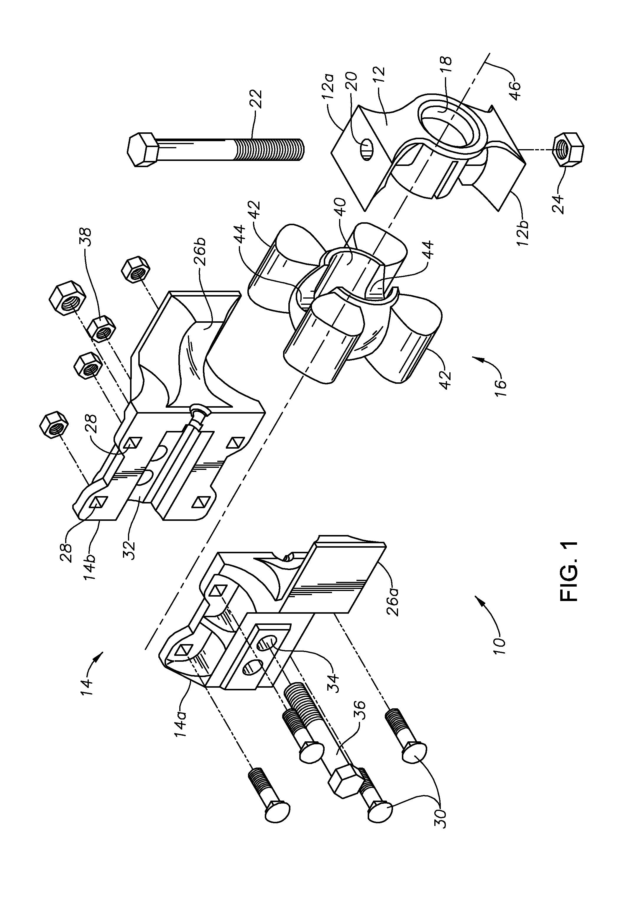
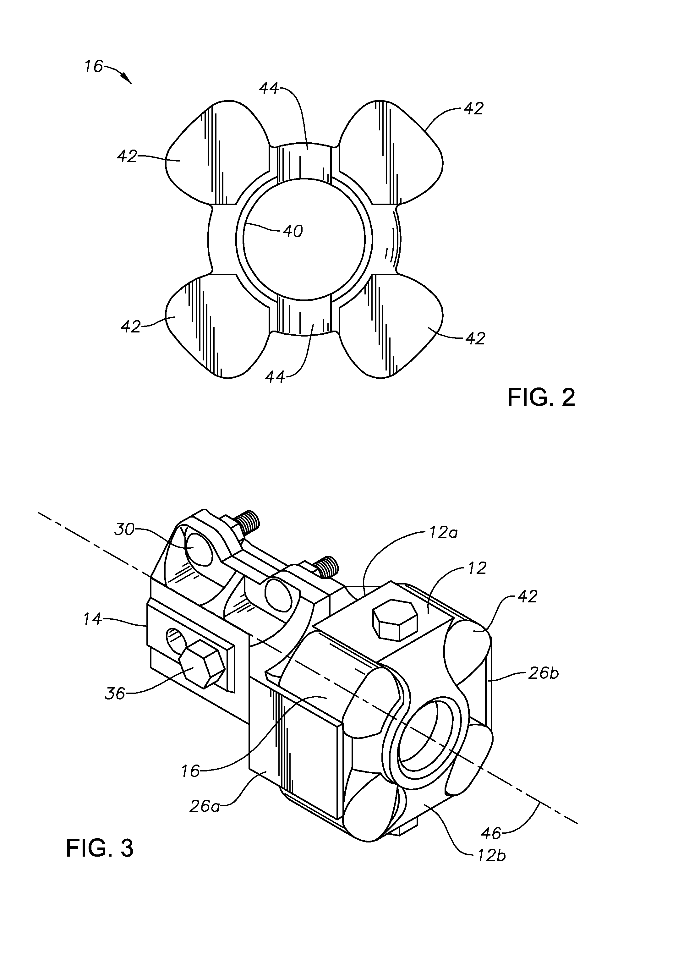
[0016]Illustrative embodiments and related methodologies of the present invention are described below as they might be employed in a drive shaft coupling mechanism. In the interest of clarity, not all features of an actual implementation or methodology are described in this specification. For example, various equipment components, such as fasteners, fittings, etc., may be omitted to simplify the description; however, those ordinarily skilled in the art will realize that such equipment can be employed as desired. It will of course be appreciated that in the development of any such actual embodiment, numerous implementation-specific decisions must be made to achieve the developers' specific goals, such as compliance with system-related and business-related constraints, which will vary from one implementation to another. Moreover, it will be appreciated that such a development effort might be complex and time-consuming, but would nevertheless be a routine undertaking for those of ordin...


PUM


Abstract

An in-line coupling device for a motor driven agricultural system utilizes less metal components while optimizing torque transfer. The device comprises a puck having a plurality of outwardly extending arms, a first shaft hub having outwardly extending flanges adapted to seat between a pair of the plurality of outwardly extending arms, and a second shaft hub having outwardly extending flanges adapted to seat between a pair of the outwardly extending arms.

Description

FIELD OF THE INVENTION[0001]The present invention relates generally to the field of power transmission for use in mechanized agricultural equipment, and more particularly to a coupler for coupling an in-line drive shaft to the wheel drive gearboxes that drive the wheels supporting and propelling an agricultural irrigation system.BACKGROUND[0002]In agricultural equipment such as irrigation systems, power mowers and the like, power is typically transferred through a gearbox from a power source, such as a motor or the PTO of a tractor, to the equipment. Typically, the drive motors or power input device has a round output shaft that is coupled to a square drive shaft of the gearbox of the equipment. In the agricultural industry, these square in-line drive shafts generally range from ¾″ to 1″ square.[0003]As with other components of agricultural equipment, the couplers utilized to inter-connect the square drive shaft with the round output shaft are often subject to extreme operating cond...

Claims


Application Information

Patent Timeline
IPC IPC(8): F16D3/40
CPCF16D3/16F16D3/68F16D1/0864
Inventor DANIEL, JEFFREY K.NEWCOMB, BRADFORD
Owner OMNI USA
Why Eureka
Try Eureka