Firearm sound suppressor

a sound suppressor and firearm technology, applied in the field of firearms, can solve the problems of affecting the two-stage sound suppression technique is relatively more complex to implement, and the overall sound level of the muzzle blast is not high enough

Inactive Publication Date: 2014-08-21
SUREFIRE LLC
View PDF3 Cites 55 Cited by
  • Summary
  • Abstract
  • Description
  • Claims
  • Application Information

AI Technical Summary

Benefits of technology

[0023]In another embodiment, a method of assembling a firearm sound suppressor includes inserting a back end member into a front aperture at a front end of a housing, wherein the housing comprises a flange at a rear end thereof that partially encloses the rear end and defines a rear aperture; and sliding the back end member to the rear end of the housing until the back end member is disposed substantially within the rear end of the housing and a rear surface of the back end member abuts an inner surface of the flange to prevent the back end member from passing through the rear aperture.
[0026]In another embodiment, a method of operating a firearm sound suppressor includes receiving combustion gases at a lumen of an interior member disposed within a housing so as to define a chamber between an exterior surface of the interior member and an interior surface of the housing; passing the combustion gases from the lumen through a plurality of vents extending through the interior member between the lumen and the chamber, receiving the combustion gases from the vents at a blast deflector disposed between the vents and the interior surface of the housing; and preventing, by the blast deflector, the combustion gases passed through the vents from impinging directly on the interior surface of the housing.
[0027]In another embodiment, a method of manufacturing a firearm sound suppressor includes providing a housing; providing an interior member; attaching a blast deflector to the interior member; and positioning the interior member with the blast deflector within the housing so as to define a chamber between an exterior surface of the interior member and an interior surface of the housing, the interior member comprising a lumen and a plurality of vents extending through the interior member between the lumen and the chamber, wherein the vents are adapted to pass combustion gases from the lumen to the chamber, wherein the blast deflector is disposed between the vents and the interior surface of the housing, wherein the blast deflector is adapted to prevent the combustion gases from impinging directly on the interior surface of the housing.
[0029]In another embodiment, a method of operating a firearm sound suppressor includes receiving a first round fired by a firearm when the firearm sound suppressor is substantially at thermal equilibrium with a surrounding environment; and reducing a size of a first muzzle flash associated with the first round by passing the first round and first associated gases through a bore of an end plate disposed at a front end of a housing of the firearm sound suppressor, wherein the bore extends through the end plate and comprises a tapered portion that opens toward a front surface of the end plate, wherein the tapered portion has an included angle in a range of approximately 10 degrees to approximately 25 degrees.

Problems solved by technology

Although this “two-stage” sound suppression technique is relatively more complex to implement, it provides more opportunities to delay and cool the propellant gases, and hence, to reduce muzzle blast sound levels overall.
Existing suppressors have certain problems that can mitigate their operation and / or efficiency.
While these deposits can usually be cleaned away with suitable solvents, they are typically hard and adhesive in nature, making it difficult or impossible to disassemble the device for cleaning without damaging its parts.
Another problem associated with certain suppressors occurs where front and rear ends of a suppressor are both implemented using end caps that are secured to a housing with threaded joints.
Unfortunately, this arrangement can complicate the removal of the suppressor from the firearm because, as the suppressor is unscrewed from the adapter or the muzzle, the torque exerted by the user on the suppressor housing can cause the rear end cap of the suppressor to unscrew from the housing, rather than from the adapter or muzzle of the firearm.
This may cause the rear end cap to remain substantially fixed on the adapter or muzzle.
As a result, the suppressor may separate and become difficult to detach completely from the firearm.
Another problem that can occur particularly with the “two-stage” type of silencers described above relates to the fact that the first stage, “blast suppressor” back sections of the devices typically experience substantially greater radial pressures and temperatures than the baffled front compartments of the devices during the firing of a single round through the device.
While this does not ordinarily present a problem when the weapon is fired intermittently, with sufficient time allowed between rounds to permit the pressure and temperature within the back section to abate, it can present a problem with sustained firing of the weapon at a relatively high rate of fire, e.g., during sustained, full automatic fire of the weapon.
In such instances, it is possible for the outer tubular housing of the device to fail prematurely, i.e., to “blow out,” due to the sustained local pressures and temperatures impinging directly thereon during such sustained, full automatic, high rates of fire.
One unsatisfactory approach to solving this problem is to increase the overall thickness of the external housing of the suppressor.
However, such an approach may significantly increase the weight of such suppressors and torque exerted on a weapon, thus hampering their usefulness.
Another problem with existing suppressors relates to their ability to function effectively as muzzle flash suppressors.
Another problem with existing suppressors relates to the mechanisms used to couple them to firearms.
This arrangement can be problematic for several reasons.
For instance, the mounting pin is cumbersome to manufacture, is prone to breakage, and cannot be easily repaired.
Further, both the pin in the suppressor and the corresponding slot in the adapter are typically positioned well within the suppressor and, therefore, are subject to a buildup of carbon, lead and copper during firing use, as described above, which can complicate disassembly and prevent proper alignment and / or seating of the adapter within the suppressor.

Method used


Image

  • Firearm sound suppressor
  • Firearm sound suppressor
  • Firearm sound suppressor

Examples


Embodiment Construction

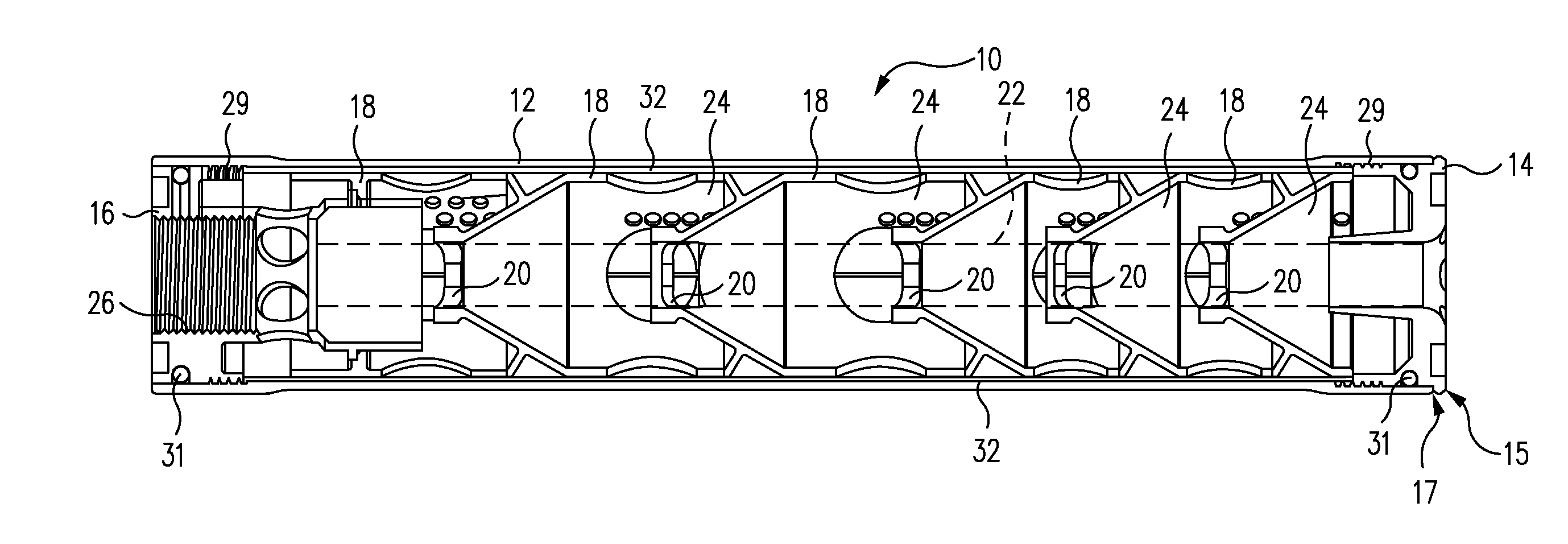
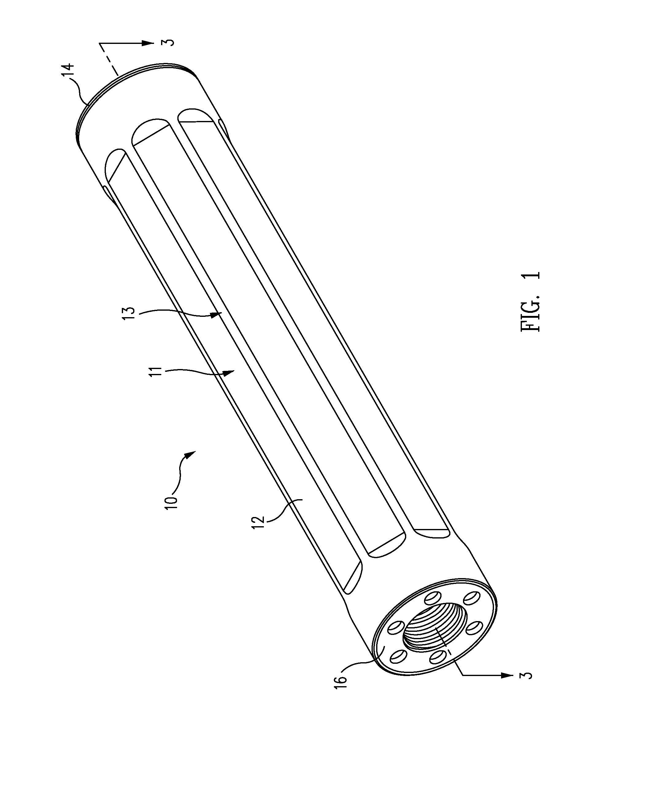
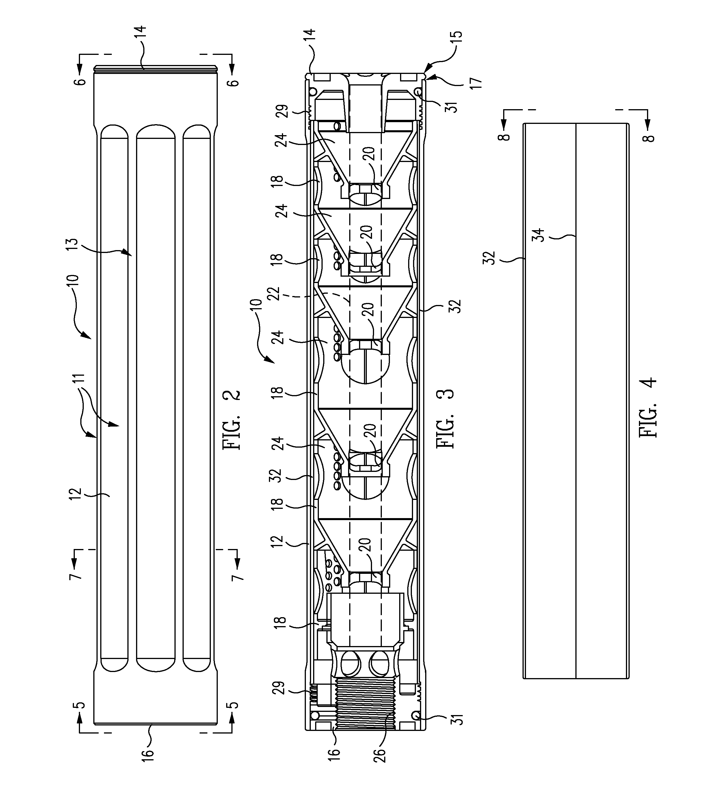
[0078]A firearm sound suppressor 10 is illustrated in the perspective, top plan, and cross-sectional views of FIGS. 1-3, respectively. As shown, the suppressor 10 includes an elongated substantially tubular housing 12, front and rear end plates 14 and 16, respectively, disposed at corresponding ends of the housing 12, and baffles 18 disposed concentrically within the housing 12 and between the two end plates 14 and 16. Although housing 12 and various other housings referred to herein are illustrated as having generally cylindrical shapes, such housings may be implemented using any shape (e.g., square, rectangular, triangular, polygonal, or others) in other embodiments as may be desired for particular applications.

[0079]In the particular embodiments illustrated in FIGS. 1-3, baffles 18 each contain a central aperture 20 and are disposed coaxially within the housing 12 such that they are distributed along the long axis thereof, with their central apertures 20 collectively defining an ...


PUM


Abstract

In one example, a firearm sound suppressor includes a housing, a baffle, and an inner sleeve adapted to be disposed within the housing and to substantially surround the baffle. The inner sleeve includes a sidewall adapted to slide against the housing to permit the inner sleeve with the baffle to be selectively inserted into and removed from the housing without the baffle contacting the housing, and a longitudinal split extending through the sidewall and between front and rear ends of the inner sleeve to permit the sidewall to flex to permit removal of the baffle from the inner sleeve. Other embodiments are also contemplated.

Description

CROSS-REFERENCE TO RELATED APPLICATIONS[0001]This application is a continuation-in-part of U.S. patent application Ser. No. 13 / 348,811 filed Jan. 12, 2012 which is hereby incorporated by reference in its entirety.[0002]This application is a continuation-in-part of U.S. patent application Ser. No. 13 / 348,834 filed Jan. 12, 2012 which is hereby incorporated by reference in its entirety.[0003]This application is a continuation-in-part of U.S. patent application Ser. No. 29 / 420,120 filed May 4, 2012 which is hereby incorporated by reference in its entirety.[0004]This application is a continuation-in-part of U.S. patent application Ser. No. 13 / 281,350 filed Oct. 25, 2011, which is a continuation-in-part of U.S. patent application Ser. No. 12 / 482,664 filed Jun. 11, 2009, all of which are hereby incorporated by reference in their entireties.[0005]U.S. patent application Ser. No. 13 / 281,350 is a continuation-in-part of U.S. patent application Ser. No. 13 / 102,819 filed May 6, 2011, which is ...

Claims


Application Information

Patent Timeline
Patent Type & Authority Applications(United States)
IPC IPC(8): F41A21/30
CPCF41A21/30F41A21/325F41A21/34
Inventor DUECK, BARRY W.HONIGMANN, KARL R.SMITH, BROOKE C.MATTHEWS, JOHN W.
Owner SUREFIRE LLC
Why Eureka
Try Eureka