
System and method for traffic side detection and characterization

a traffic detection and traffic side technology, applied in the field of optical systems, can solve the problems of high failure rate and inflexibility, high cost, and limitations, and achieve the effect of high repetition ra

Active Publication Date: 2014-08-21
LEDDARTECH INC
View PDF19 Cites 58 Cited by
  • Summary
  • Abstract
  • Description
  • Claims
  • Application Information

AI Technical Summary

Benefits of technology

The present invention provides a method for detecting a vehicle in a detection zone of a roadway using a multi-channel scannerless full-waveform lidar system. The method involves emitting pulses of light and receiving reflections of the pulses from the detection zone. An initialization parameter is provided for the system and a time-spaced individual complete trace is acquired. The individual complete trace is compared with a series of other traces to identify the presence of a vehicle. The method can detect the vehicle based on its height and intensity, and can also track its movement. The invention can be used to detect environmental particles, such as fog, water, and dust, and can identify the position of a vehicle in the detection zone. The method can be used in roadways with a single lane or multiple lanes.

Problems solved by technology

Commercial vehicles can also have other constraints such as truck lane restrictions specifying on which lane a certain type of vehicle is allowed to travel, to requiring classification functionality from the detection system.
One type of intrusive detectors involves inductive loop detectors that are still a common technology for detecting vehicles even if that technology has some disadvantages such as lengthy disruption to the traffic flow during installation and maintenance, relatively high cost, high failure rate and inflexibility.
Other detectors, like cameras with video processing, radar-based sensors, laser-based sensors, passive infrared and ultrasound sensors have been introduced for traffic monitoring but also have their limitations and the market is still searching for alternatives.
Video processing sensors have well know drawbacks such as the lack of performance in terms of false alarms during night operation or the difficulty to perform during bad weather conditions affecting visibility such as during an episode of fog.
Environmental particles are known to be difficult to manage.
Radar technology is known to perform well in bad weather conditions but has some limitations in terms of lateral resolution.
Accurate occupancy measurement can be limited when occupancy is high.
In some cases, for measuring the speed of a vehicle, radar traffic detectors located on the side of the road use an average length for the vehicles which causes errors in the vehicle speed estimate.

Method used


Image

  • System and method for traffic side detection and characterization
  • System and method for traffic side detection and characterization
  • System and method for traffic side detection and characterization

Examples


Embodiment Construction

1. Use, Set-Up, Basic Principles and Features

[0072]Reference will now be made in detail to examples. The system and method may however, be embodied in many different forms and should not be construed as limited to the example embodiments set forth in the following description.

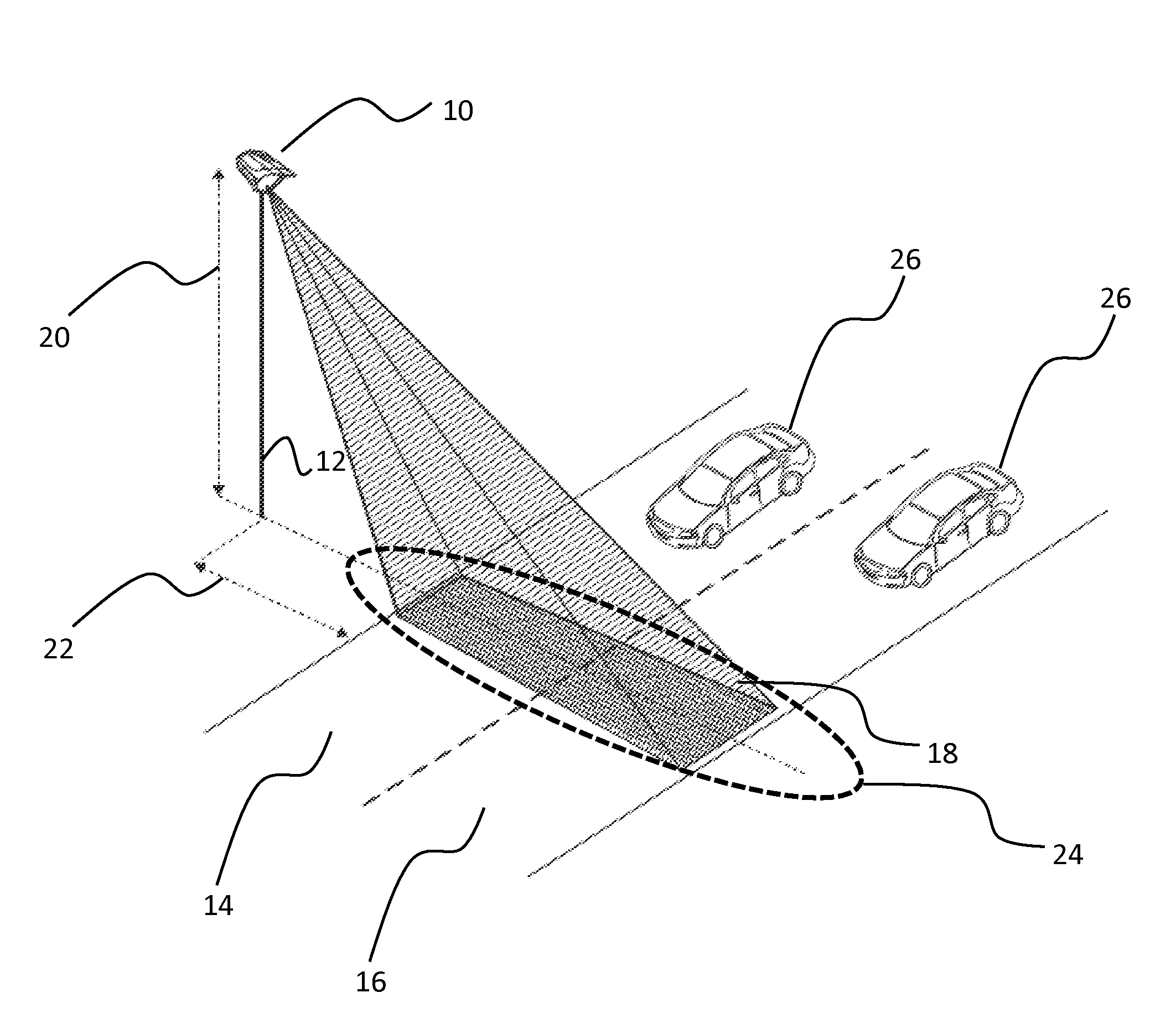
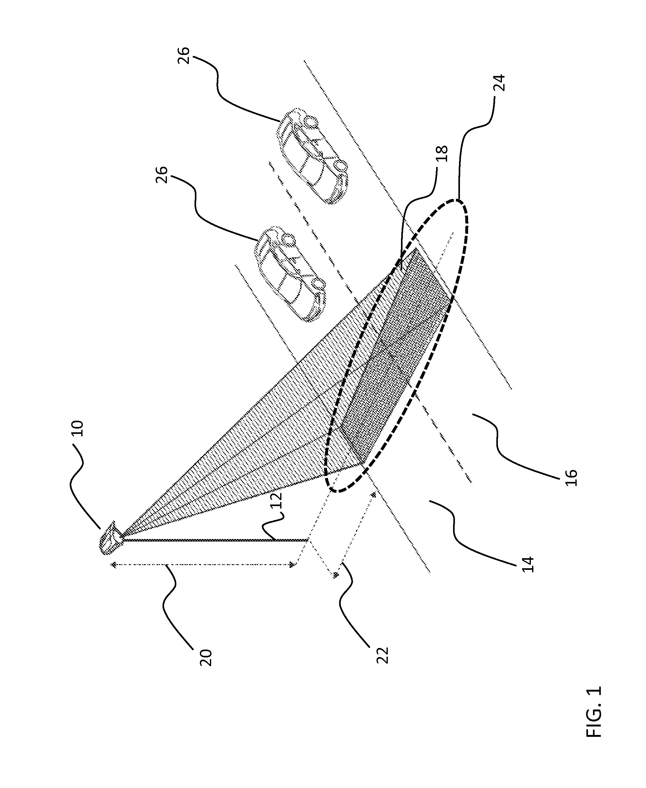
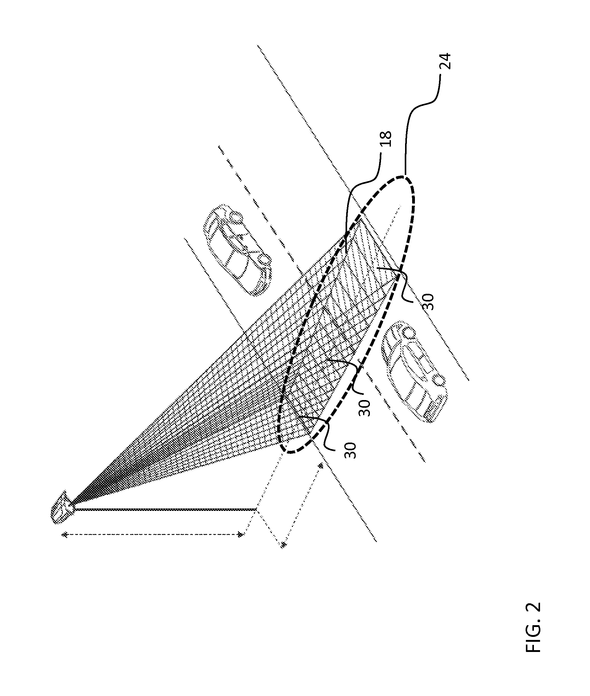
[0073]An example mounting configuration of the traffic detection system 10 can be appreciated with reference to FIG. 1, which depicts a schematic view of a roadway with two to lanes being shown. The traffic detection system 10 is shown in FIG. 1 mounted on a pole 12. The system casing can have a perpendicular orientation to the traffic direction. Pole 12 can be a new dedicated road infrastructure for the sensor installation, an existing road infrastructure or other types of new or existing infrastructures such as streetlights, gantries or buildings. This exemplary roadway comprises two adjacent traffic lanes 14 and 16 for vehicles. In this example, the traffic lanes 14 and 16 are for incoming traffic. The traff...


PUM


Abstract

A method for detecting a vehicle comprising: providing a multi-channel scannerless full-waveform lidar system operating in pulsed Time-Of-Flight operation oriented towards a surface of the roadway to cover the detection zone; providing at least one initialization parameter; emitting pulses at an emission frequency; receiving reflections of the pulses from the detection zone; and acquiring and digitalizing a series of individual complete traces at each channel of system; identifying at least one detection in at least one of the traces; obtaining a height and an intensity for the detection; determining a nature of the detection to be one of an environmental particle detection, a candidate object detection and a roadway surface detection; if the nature of the detection is the candidate object detection, detecting a presence of a vehicle in the detection zone.

Description

CROSS-REFERENCE TO RELATED APPLICATIONS[0001]This application claims priority under 35 USC §119(e) of U.S. provisional patent application 61 / 498,083 filed Jun. 17, 2011, the specification of which is hereby incorporated by reference.TECHNICAL FIELD[0002]The present invention relates to a system and method for traffic detection and more particularly to an optical system that detects the presence of vehicles on a roadway regardless of environmental particles present in the field of view using an active three-dimensional sensor based on the time-of-flight ranging principle.BACKGROUND OF THE ART[0003]Information from sensors is the base point in the optimization of traffic management and law enforcement. Using sensors allows gathering statistical data about different parameters related to traffic monitoring and detecting traffic infractions like speed limit violations. Examples of interesting parameters to track are detecting the presence of a vehicle in a detection zone, counting the n...

Claims


Application Information

Patent Timeline
Patent Type & Authority Applications(United States)
IPC IPC(8): G08G1/048G08G1/056G01S7/48G01S17/88G01S17/02G08G1/04G08G1/052G01S7/4865G01S17/04G01S17/10G01S17/86G01S17/894
CPCG08G1/048G08G1/04G08G1/056G01S7/4808G01S17/88G01S17/026G08G1/052G01S7/4802G01S17/10G01S7/4865G01S17/04G01S17/86G01S17/894G06V20/54
Inventor MIMEAULT, YVANGIDEL, SAMUELPOULIN, MICHAELARROUART, DAVID
Owner LEDDARTECH INC
Learn More