Powder filling device with redundant powder collection mechanism, and rotary compression molding machine

a filling device and powder collection technology, applied in the field of powder filling devices with redundant powder collection mechanism, rotary compression molding machines, can solve the problems of not being applicable, not being able to describe specific recovery methods and uniform mixing methods, and not being able to apply methods, etc., to achieve active recovery and reuse of redundant powdery materials.

Active Publication Date: 2014-08-21
SANWAKAGUKU KENKYUSHO CO LTD +1
View PDF3 Cites 4 Cited by
  • Summary
  • Abstract
  • Description
  • Claims
  • Application Information

AI Technical Summary

Benefits of technology

The invention allows for the active recovery and reuse of redundant powdery materials even when multiple powdery materials are used in a rotary compression molding machine. This results in consistent quality of molded products from different powdery materials. The powdery material filling device with the redundant powdery material recovering mechanism can actively recover and reuse the redundant powdery material even when producing multi-layer tablets where powdery materials in different layers must not be mixed.

Problems solved by technology

In other words, Non-Patent Document 1 fails to describe any specific recovering means and any uniformly mixing means.
In a case where there are a plurality of powdery material supply devices in order to produce multi-layer tablets or multi-layer products, such a technique is not applicable to the means for circulating a powdery material and recovering the powdery material on a rotating die table because a plurality of powdery materials are mixed together.
This method is not applicable to a case where segregation seriously influences the quality such as non-uniformity of medicinal properties contents (drug contents) as in mixed powdery materials used for molding tablets containing medicinal properties.
In this case, it is impossible to achieve homogenization and prevent segregation of the powdery material.
As described above, all of these conventional techniques relate to compression molding of a single type of powdery material and are not applicable to a case where a rotary compression molding machine having a plurality of feeders produces a molded product by compressing and molding a plurality of types of powdery materials.

Method used


Image

  • Powder filling device with redundant powder collection mechanism, and rotary compression molding machine
  • Powder filling device with redundant powder collection mechanism, and rotary compression molding machine
  • Powder filling device with redundant powder collection mechanism, and rotary compression molding machine

Examples


Embodiment Construction

[0035]An embodiment of the invention is described below with reference to the accompanying drawings. The invention is not limited to the following embodiment but includes various combinations of any of examples. The invention can be embodied with free modification within the scope of the description as well as the scope of common technical knowledge.

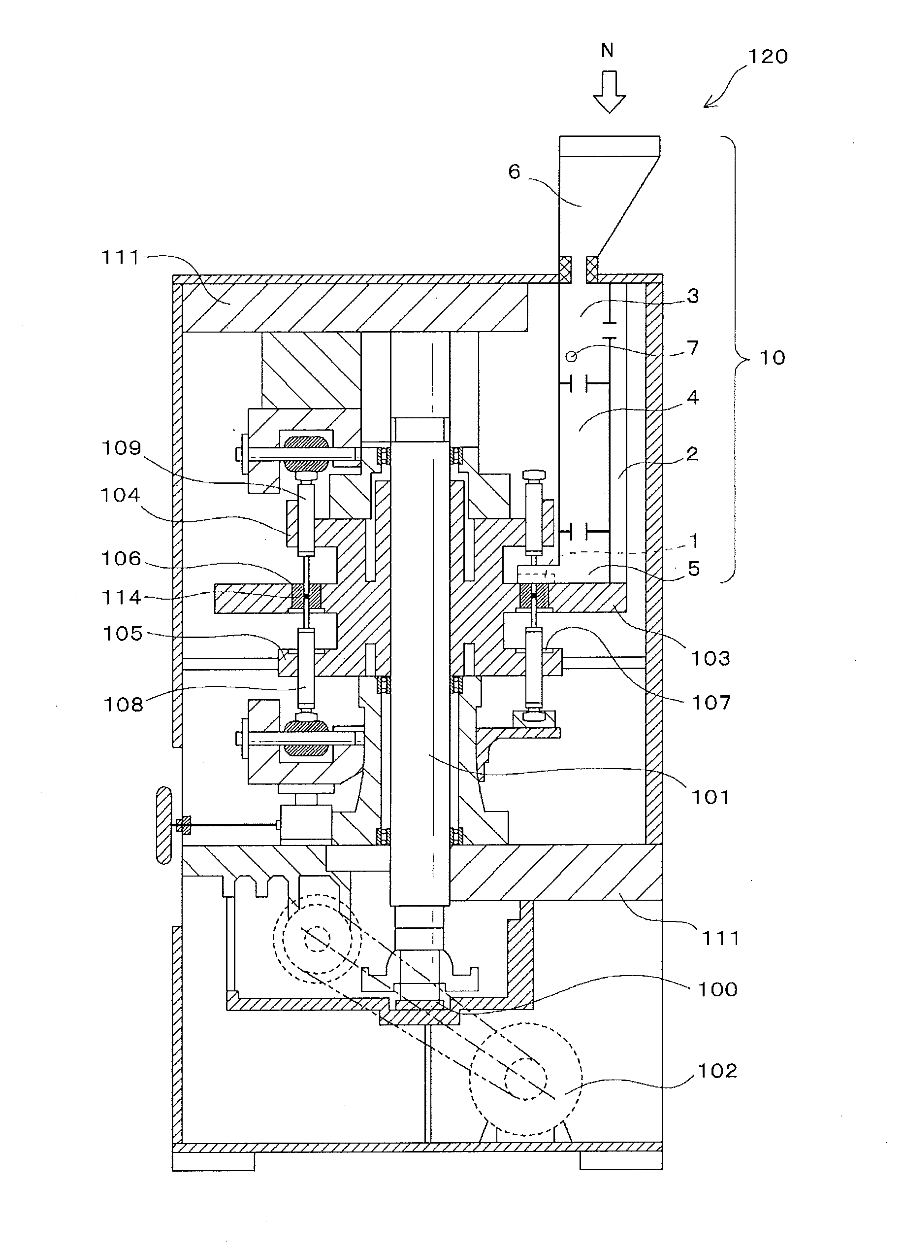
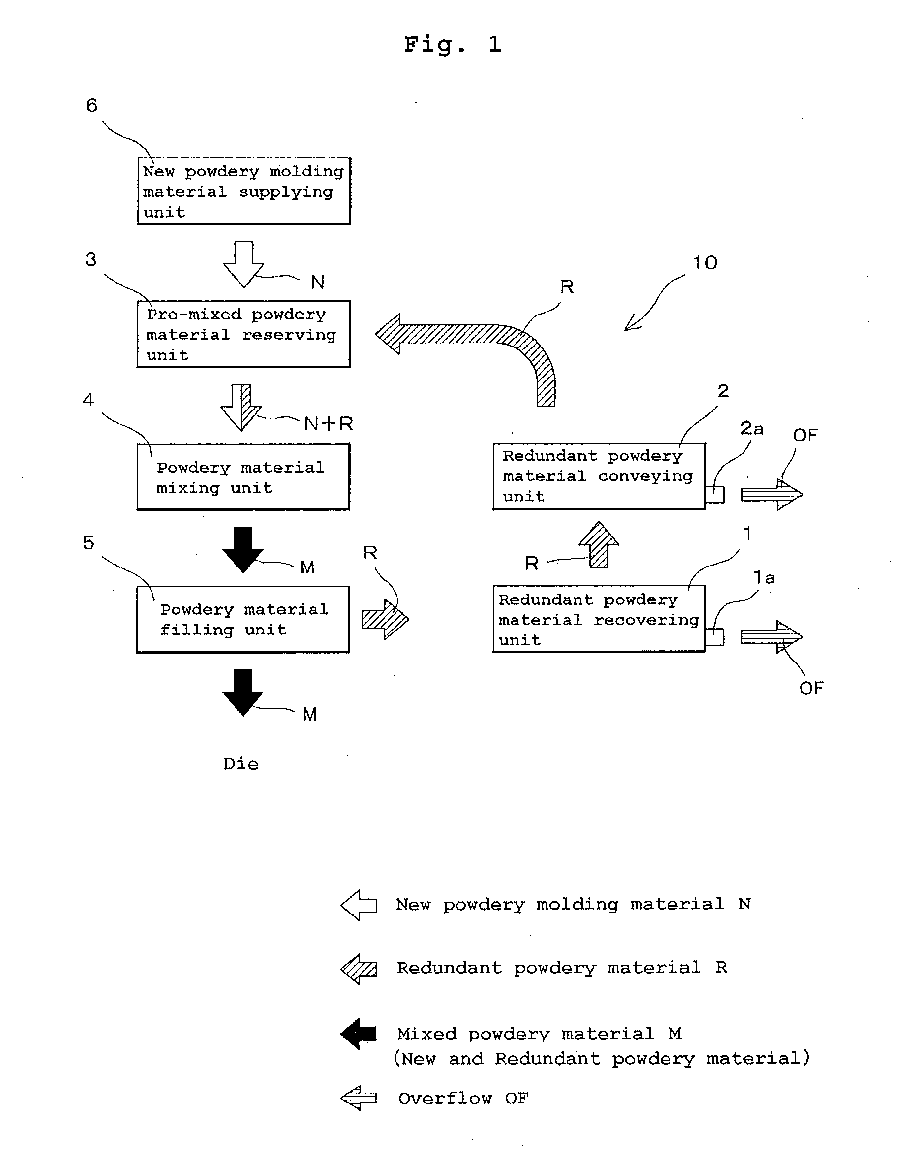
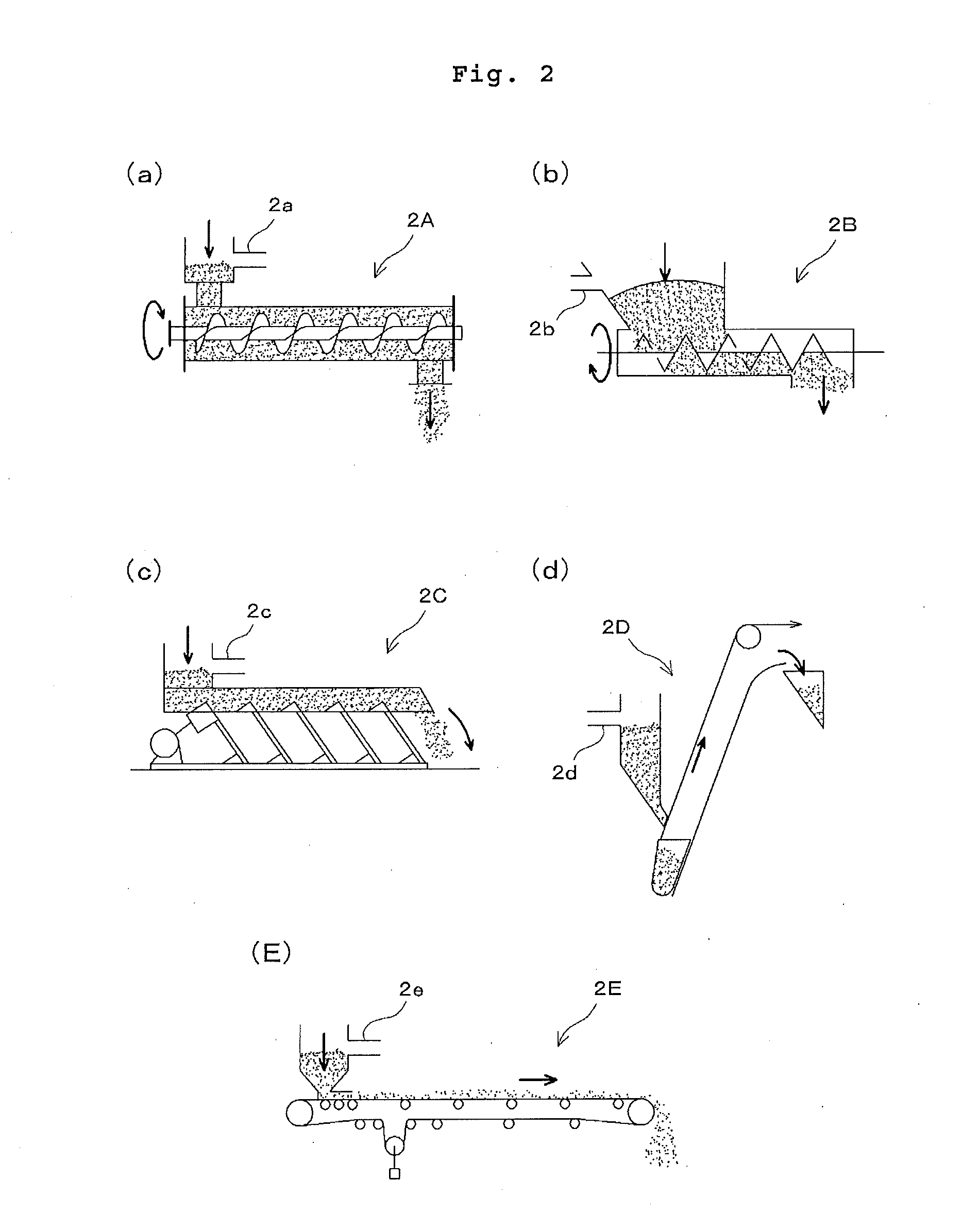
[0036]FIG. 1 is a flowchart showing a flow of powdery materials in an exemplary filling device provided with a redundant powdery material recovering mechanism according to the invention. FIG. 1 shows a powdery material filling device 10 provided with a redundant (i.e., excess or waste) powdery material recovering mechanism. The filling device 10 is included in a rotary compression molding machine (of which configuration is to be detailed later), having a rotating die table provided with a plurality of dies, and upper punches and lower punches located above and below the dies respectively, wherein the dies are filled with powdery material...


PUM

PropertyMeasurementUnit
Structureaaaaaaaaaa
Hardnessaaaaaaaaaa

Abstract

Disclosed is a powdery material filling device with a redundant (i.e., excess or waste) powdery material recovering mechanism. The powdery material filling device may be used in a rotary compression molding machine. In certain aspects, the redundant powdery material recovering mechanism is capable of actively recovering and reusing a redundant (i.e., excess or waste) powdery material even upon production of multi-layer tablets.

Description

TECHNICAL FIELD[0001]The invention relates to a powdery material filling device provided with a redundant (i.e., excess or waste) powdery material recovering mechanism for use in a rotary compression molding machine having a rotating die table provided with a plurality of dies, and upper punches and lower punches located above and below the dies respectively, wherein the dies are filled with powdery material and then the upper punches and the lower punches compress and mold the filled powdery material in the dies sequentially while the dies, the upper punches, and the lower punches are being rotated along with the rotating die table. The invention also relates to the rotary compression molding machine having the filling device.BACKGROUND[0002]Non-Patent Document 1 depicts a gravity feeder in FIG. 7.40 and describes “In order to achieve uniform filling, empirically known is that it is important to appropriately set a ratio of a new material and an old material having circulated in a ...

Claims


Application Information

Patent Timeline
IPC IPC(8): B29B17/00B29C43/34
CPCB29C43/34B29B17/0005B30B11/08B30B15/302B30B15/0082B30B11/005
Inventor OZEKI, YUICHIIZUMI, KENTAROFUJISAKI, KATSUHITOATAGI, KOUICHI
Owner SANWAKAGUKU KENKYUSHO CO LTD
Why Eureka
Try Eureka