
Expandable fusion device for positioning between adjacent vertebral bodies

Active Publication Date: 2014-08-21
FLEXUSPINE
View PDF13 Cites 207 Cited by
  • Summary
  • Abstract
  • Description
  • Claims
  • Application Information

AI Technical Summary

Benefits of technology

The patent describes an expandable device that can be placed between adjacent vertebral bodies to promote bone growth and spine fusion. The device can be adjusted to the preferred height for an individual patient with minimal force application. It includes a cage, superior and lower bodys, and an expansion mechanism with opposing proximal and second expansion members. The device can be expanded or contracted to increase or decrease its height, respectively, by applying torque to the expansion mechanism in one direction or the other. The superior and lower bodys may also have protrusions that help retain the device between the first and second vertebral bodies after insertion.

Problems solved by technology

However, genetic or developmental irregularities, trauma, chronic stress, and degenerative wear can result in spinal pathologies for which surgical intervention may be necessary.
More particularly, the discs sometimes become diseased or damaged such that the height of the disc is reduced, which causes the annulus to buckle in areas where the laminated plies are loosely bonded.
Such practices are characterized by certain disadvantages, including the need to distract the disc space in order to implant the fusion device and thereby restore the diseased disc space to its normal or healthy height.
However, it can be difficult to distract the adjacent vertebral bodies sufficiently to easily insert the fusion device between adjacent vertebral bodies.
As a result, it is often necessary to drive the fusion device into the space between the vertebral bodies using impaction with a mallet and the application of significant force.
The use of such impaction and force increases the risk of damage to local soft tissue such as blood vessels and the surrounding nerves, and can lead to suboptimal placement and / or failure of the insertion instrumentation.
Furthermore, the use of such impaction and force can damage or compromise the vertebral endplates, resulting in eventual failure and subsidence of the fusion device into the vertebral bodies and hence loss of disc height.

Method used


Image

  • Expandable fusion device for positioning between adjacent vertebral bodies
  • Expandable fusion device for positioning between adjacent vertebral bodies
  • Expandable fusion device for positioning between adjacent vertebral bodies

Examples


Embodiment Construction

Definitions

[0069]Unless defined otherwise, all technical and scientific terms used herein have the same meaning as commonly understood by one of ordinary skill in the art.

[0070]The term “connected” as used herein generally refers to pieces which may be joined or linked together.

[0071]The term “coupled” as used herein generally refers to pieces which may be used operatively with each other, or joined or linked together, with or without one or more intervening members.

[0072]The term “directly” as used herein generally refers to one structure in physical contact with another structure, or, when used in reference to a procedure, means that one process effects another process or structure without the involvement of an intermediate step or component.

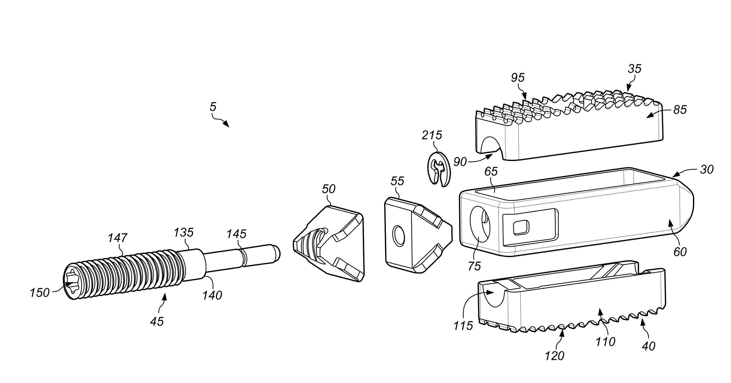
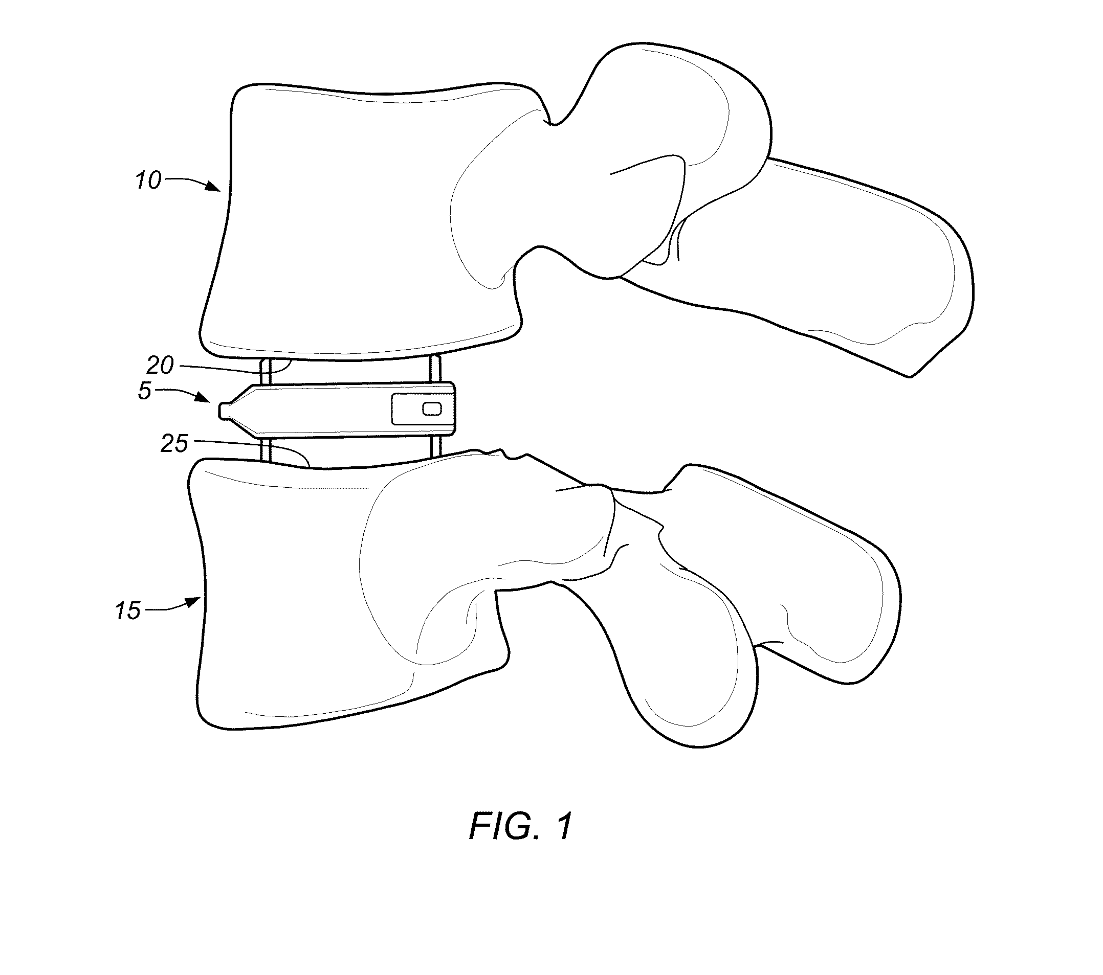
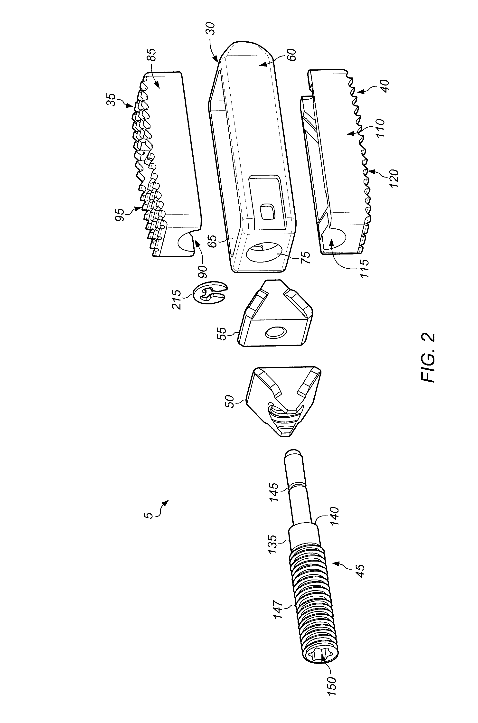
[0073]Looking first at FIG. 1, there is shown an intervertebral implant 5 (e.g., expandable fusion device) formed in accordance with the present invention, with the intervertebral implant 5 being shown disposed between a superior vertebral bod...


PUM


Abstract

In some embodiments, system and / or method may include an intervertebral implant for a human spine including an upper body, a lower body, first and second expansion members, and an expansion mechanism. A superior surface of the upper body may function to engage a first vertebra of the human spine. An inferior surface of the lower body may function to engage a second vertebra of the human spine. The first expansion member may include at least a first angled portion positionable, during use, between the upper body and the lower body. The second expansion member may include at least a second angled portion positionable, during use, between the upper body and the lower body. An expansion mechanism may convey, during use, the first and second angled portions in opposing directions increasing a separation distance between the upper body and the lower body.

Description

PRIORITY CLAIM[0001]This application claims priority to U.S. Provisional Patent Application No. 61 / 766,982 entitled “EXPANDABLE FUSION DEVICE FOR POSITIONING BETWEEN ADJACENT VERTEBRAL BODIES” filed on Feb. 20, 2013, which is incorporated by reference herein.BACKGROUND OF THE INVENTION[0002]1. Field of the Invention[0003]This invention relates to spinal implant devices and methods for promoting fusion between adjacent vertebral bodies, and more particularly to expandable fusion devices that can be inserted between adjacent vertebral bodies to facilitate the fusion thereof.[0004]2. Description of the Relevant Art[0005]The human spine is a complex mechanical structure, composed of alternating bony vertebrae and fibrocartilaginous discs that are connected by strong ligaments and supported by musculature, that extends from the skull to the pelvis and provides axial support for the body.[0006]The vertebrae generally comprise a vertebral foramen bounded by the anterior vertebral body and ...

Claims


Application Information

Patent Timeline
IPC IPC(8): A61F2/44
CPCA61F2/447A61F2/4455A61F2/4465A61F2/4611A61F2002/2835A61F2002/30507A61F2002/30556A61F2002/30772A61F2002/30904A61F2002/4627
Inventor WAGNER, ERIKSCHULAR, MICHAEL
Owner FLEXUSPINE
Learn More