Electromagnetically actuated multi-leaf collimator

a collimator and electromagnetic field technology, applied in the field of radiotherapy, can solve the problems of long patient treatment, slow movement of leaves defining shapes, and limiting the ability of conventional shaping-mlc's to deliver time-sensitive treatments

Active Publication Date: 2014-08-28
TOMOTHERAPY INC +1
View PDF36 Cites 64 Cited by
  • Summary
  • Abstract
  • Description
  • Claims
  • Application Information

AI Technical Summary

Benefits of technology

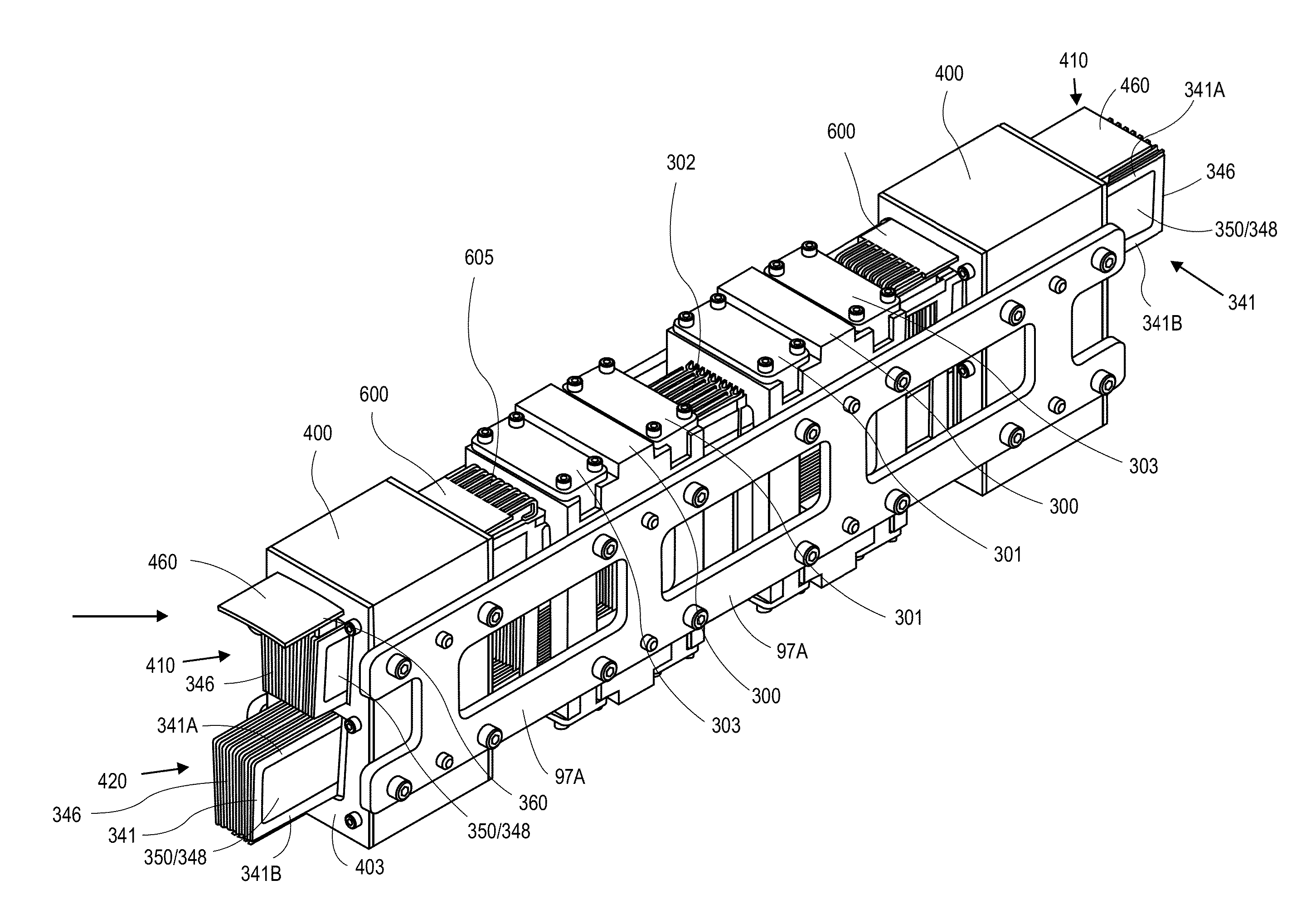
[0013]Embodiments of the present invention provide a multi leaf collimator (MLC). These embodiments have a plurality of leaves having a length of travel. Each leaf has a proximal end, a distal end, a radio opaque distal blocking portion having a length L and width W, a proximal drive portion having a length L′ and width W′, one or more conductive coils fixed to the proximal drive portion and operatively connected to an electrical current source, where electrical current passing through the conductive coils generates a first magnetic field. The MLC of these embodiments also have a leaf guide with a plurality of channels arranged approximately parallel and adjacent to each other where at least a portion of each of the plurality of leaves is slidingly arranged into each of said channels, and a plurality of stationary magnets positioned adjacent to the proximal drive portion, where each stationary magnet has a second magnetic field configured to operate in conjunction with the first magnetic field from the coils to exert a force on the proximal drive portion. In some embodiments the MLC will have dual opposing banks of leaves, and other embodiments will have the stationary magnets on either side of the drive portion.

Problems solved by technology

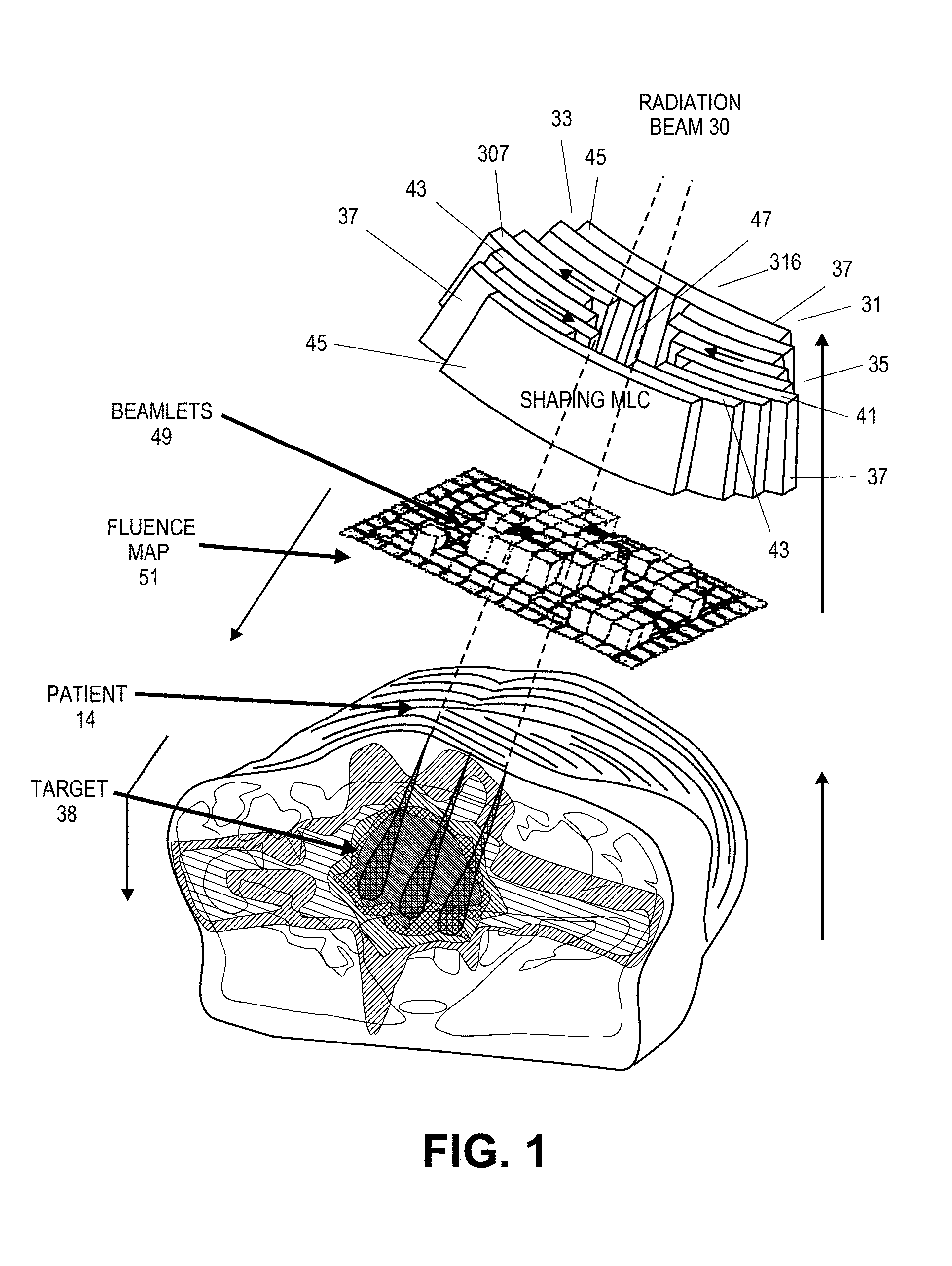
A common limitation of the conventional shaping MLC is that the leaves defining the shapes move relatively slowly.
Using large numbers of shapes, or shapes that require large leaf motions, can result in longer patient treatments.
Likewise, the speed of the leaves can limit the ability of conventional shaping-MLC's to deliver time-sensitive treatments, such as utilizing synchronized motion of delivery components (e.g., gantry, couch, x-ray energy etc.).
While multi-leaf collimators exist, the speed and control of an individual leaf or group of leaves is insufficient to achieve more advanced simultaneous shaping and modulating beam patterns.

Method used


Image

  • Electromagnetically actuated multi-leaf collimator
  • Electromagnetically actuated multi-leaf collimator
  • Electromagnetically actuated multi-leaf collimator

Examples


Embodiment Construction

[0044]Before any embodiments of the invention are explained in detail, it is to be understood that the invention is not limited in its application to the details of construction and the arrangement of components set forth in the following description or illustrated in the following drawings. The invention is capable of other embodiments and of being practiced or of being carried out in various ways. Also, it is to be understood that the phraseology and terminology used herein is for the purpose of description and should not be regarded as limiting. The use of “including,”“comprising,” or “having” and variations thereof herein is meant to encompass the items listed thereafter and equivalents thereof as well as additional items. Unless specified or limited otherwise, the terms “mounted,”“connected,”“supported,” and “coupled” and variations thereof are used broadly and encompass both direct and indirect mountings, connections, supports, and couplings. Further, “connected” and “coupled”...


PUM


Abstract

A multi-leaf collimator with electromagnetically actuated leaves. The multi-leaf collimator includes a plurality of leaves, a leaf guide configured to support the plurality of leaves, and a plurality of magnets. Each leaf includes a blocking portion that is radio opaque, a drive portion connected to the blocking portion, and a coil embedded in the drive portion. The coil is operatively connected to an electrical current source to generate a first magnetic field. The first magnetic field interacts with the magnetic field generated by the magnet to thereby move the leave to a desired state. The leaves have the capability of moving at speeds of 50 cm/s up to and higher than 1 m/s.

Description

CROSS-REFERENCE TO RELATED APPLICATIONS[0001]This application is a non-provisional of and claims priority to U.S. Provisional Application No. 61 / 769,549, filed on Feb. 26, 2013. The contents of Application No. 61 / 769,549 are incorporated herein by reference. All publications and patent applications mentioned in this specification are herein incorporated by reference to the same extent as if each individual publication or patent application was specifically and individually indicated to be incorporated by reference.FIELD OF THE INVENTION[0002]The present invention generally relates to radiation therapy. In various respects, the invention is directed to a highly responsive multileaf collimator, and method of use to provide radiation therapy utilizing beam shaping, intensity modulation and combinations thereof including simultaneous beam shaping and intensity modulation of therapeutic beams.BACKGROUND OF THE INVENTION[0003]Intensity modulated radiotherapy (commonly referred to as IMRT)...

Claims


Application Information

Patent Timeline
Patent Type & Authority Applications(United States)
IPC IPC(8): G21K1/02
CPCG21K1/025A61N5/1031A61N5/1045A61N5/1048A61N5/1071G21K1/046A61N2005/1092
Inventor ORTON, MATTHEW J.MASTROMATTEI, ROBERTO'CONNELL, ROBERTSCHMIDT, RICHARD C.REITZ, GRAHAM
Owner TOMOTHERAPY INC
Why Eureka
Try Eureka