Multi-leaf collimator and a radiotherapy unit provided with the same

a collimator and multi-leaf technology, applied in the direction of optical radiation measurement, instruments, therapy, etc., can solve the problems of backlash at each of the gears, errors due to backlash between the detected locations of leaf blocks and the actual locations, and the tops of teeth become worn, so as to achieve high precision and high precision

Inactive Publication Date: 2007-08-02
TOSHIBA MEDICAL SYST CORP
View PDF6 Cites 24 Cited by
  • Summary
  • Abstract
  • Description
  • Claims
  • Application Information

AI Technical Summary

Benefits of technology

[0011]This invention is intended to provide a multi-leaf collimator that avoids the effect of backlash in detecting the displacement or locations of leaf blocks and that precisely detects the displacement or locations of leaf blocks and to provide the radiotherapy unit provided with the same.
[0014]According to the first and second aspects 1 and 2 of this invention, the displacement and locations of the leaf blocks can be detected without making contact, and errors due to the effect of backlash and gear wear in detecting the displacement and the locations can be prevented. Therefore, regardless of backlash, the locations of leaf blocks can be detected with high precision, and the radiation field can be matched to the shape of the affected part with high precision.

Problems solved by technology

Thus, if a movable mechanism comprises a plurality of gears as above, backlash occurs at each of the gears.
With the method of detecting the locations of the leaf blocks based on rotation of one of the multiple gears, errors due to backlash are observed between the detected locations of the leaf blocks and the actual locations thereof.
However, gears engage with each other physically, so the tops of the teeth become worn over time.
As this wear progresses over time, errors caused by backlash will increase.
Therefore, even if the locations are corrected with pre-calculated backlash, errors will gradually increase, resulting in decreased accuracy of specifying the locations of the leaf blocks over time.
Therefore, errors in detected locations caused by backlash affect therapeutic effectiveness to a considerable degree.

Method used


Image

  • Multi-leaf collimator and a radiotherapy unit provided with the same
  • Multi-leaf collimator and a radiotherapy unit provided with the same
  • Multi-leaf collimator and a radiotherapy unit provided with the same

Examples


embodiment 1

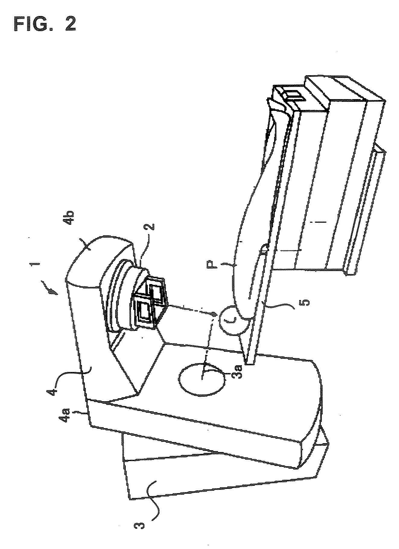
[0033]FIG. 2 is an external view showing a radiotherapy unit 1 related to this embodiment. The radiotherapy unit 1 is an apparatus for treating the affected part of an object P. The radiotherapy unit 1 treats the affected part by emitting radiation at the affected part of the object P.

[0034]This radiotherapy unit 1 is provided with a radiation head 2 that generates radiation and a bed 5 on which the object P is placed. The radiation head 2 and bed 5 are arranged facing each other. Radiation generated in the radiation head 2 is emitted in the direction toward the bed 5.

[0035]This radiotherapy unit 1 is fixed with a fixing gantry 3 on the surface on which the apparatus is installed. A rotating gantry 4 is supported by this fixing gantry 3 in the air. The radiation head 2 is installed on this rotating gantry 4. The rotating gantry 4 is a rough L-shaped steric figure. The rotating gantry 4 has an arm 4a supported by the fixing gantry 3, and the radiation head 2 is installed on the other...

embodiment 2

[0086]Next, Embodiment 2 of the radiotherapy unit 1 of the present invention will be described. Furthermore, the same codes are used for the same structures and same functions as in Embodiment 1, so detailed descriptions are omitted. The radiotherapy unit 1 of this embodiment detects the location of the leaf block 23B with the detecting element 25.

[0087]FIG. 12 is a view showing the pattern image 231 drawn on the outer circumferential arc surface of the leaf block 23B. In the radiotherapy unit 1 of this embodiment, one pattern image 231 is drawn along the longitudinal direction, or in other words along the direction of movement of the leaf block 23B, on the outer circumferential arc surface of the leaf block 23B. The pattern image 231 is extended across the same width as the movable range of the leaf block 23B.

[0088]This pattern image 231 has a plurality of location-specific patterns 231b in parallel at predetermined intervals. These location-specific patterns 231b express location-...

embodiment 3

[0108]Next, Embodiment 3 of the radiotherapy unit 1 of the present invention will be described. The same codes are used for the same structures and same functions as Embodiments 1 and 2, so detailed descriptions are omitted. The radiotherapy unit 1 of this embodiment detects displacement and detects locations in a similar manner as in Embodiments 1 or 2.

[0109]FIG. 16 is a view showing locations of the arranged irradiation part 26 and the image sensor 27. In the radiotherapy unit 1 of this embodiment, a pair of the irradiation part 26 and the image sensor 27 for detecting the displacement or location of the same leaf block 23B and a pair of the irradiation part 26 and the image sensor 27 corresponding to the adjacent leaf block 23B, are differently arranged in lines.

[0110]As shown in FIG. 16(a), for example, pairs of the irradiation parts 26 and the image sensors 27 corresponding to each of the leaf blocks 23B are arranged alternately in two lines so that the adjacent pairs of the ir...


PUM


Abstract

A multi-leaf collimator that narrows a radiation field to a predetermined shape is provided with leaf blocks movable in the direction of the radiation field and having pattern images drawn along the direction of movement on a predetermined surface, and detection part acquiring an image of fixed-point via fixed-point observation in the direction of that predetermined surface and for detecting displacement of said leaf blocks based on the arranged locations of the pattern images existing in this image of fixed-point. Moreover, it is provided with detection part acquiring an image of fixed-point via fixed-point observation in the direction of that predetermined surface and for detecting the locations of the leaf blocks based on the arranged locations of the pattern images existing in this image of fixed-point. According to the present invention, displacement and locations of leaf blocks can be detected without making contact, and displacement due to the effect of backlash and gear wear or errors in detecting locations can be prevented. Therefore, regardless of backlash, the locations of the leaf blocks can be detected with high precision, and the radiation field can be matched to the shape of an affected part with high precision.

Description

BACKGROUND OF THE INVENTION[0001]1. Field of the Invention[0002]The present invention relates to a multi-leaf collimator that narrows the radiation field emitted to an object and a radiotherapy unit provided with the same.[0003]2. Description of the Related Art[0004]Radiation therapy has been widely used as treatment for affected parts such as cancer and tumors. This radiation therapy is treatment with the destruction of tissue cells in an affected part, inhibition of cell division, or the like by emitting radiation to the affected part. It is important to precisely irradiate an affected part in such radiation therapy. By precisely irradiating an affected part, damage to normal cells around an affected part can be minimized, thereby enabling effective irradiation to an affected part.[0005]In order to ensure precise irradiation, generated radiation is narrowed with a diaphragm part or multi-leaf collimator so that the shape of the radiation field becomes similar to that of the affect...

Claims


Application Information

Patent Timeline
Patent Type & Authority Applications(United States)
IPC IPC(8): G01J1/00
CPCA61N5/1042G21K1/046G21K1/04A61N5/1048A61N2005/1095
Inventor HASHIMOTO, TERUO
Owner TOSHIBA MEDICAL SYST CORP
Why Eureka
Try Eureka