User interface display device

a display device and user interface technology, applied in the direction of static indicating devices, image enhancement, instruments, etc., can solve the problems of unnatural or unsmooth hand motion of operators, and achieve the effects of reducing psychological burdens on operators, simple facilities, and sufficient detection

Inactive Publication Date: 2014-08-28
NITTO DENKO CORP
View PDF3 Cites 19 Cited by
  • Summary
  • Abstract
  • Description
  • Claims
  • Application Information

AI Technical Summary

Benefits of technology

[0009]The present inventor has diligently made studies to solve the aforementioned problem, and has hit upon the idea of shooting a hand with a small number of cameras distant from a spatial image for the purpose of reducing psychological burdens on an operator during an input operation using the hand. The present inventor has focused attention on the motion (image) of the hand during the shooting with the cameras, and has made further studies. As a result, the present inventor has found that the motion of the hand serving as an input body is sufficiently detected with a simple configuration having a single camera by placing a display and an optical panel for image-forming the display on the display in a predetermined positional relationship to project the display (spatial image) appearing on the display in space above the aforementioned optical panel and by shooting the hand inserted around the aforementioned spatial image with an optical imaging means such as a camera disposed below or above the spatial image to identify the position or coordinates of the aforementioned hand based on this image. Hence, the present inventor has attained the present invention.
[0010]The present invention has been made based on the aforementioned findings. The user interface display device according to the present invention includes a flat panel display for displaying a video picture, and an optical panel such as a lens for projecting a video picture in space. The aforementioned optical panel is disposed in parallel with a virtual horizontal plane based on an operator so that the optical axis of the optical panel is orthogonal to the virtual horizontal plane. The aforementioned flat panel display is disposed below the aforementioned optical panel in such an attitude that the display surface thereof is inclined and is positioned to face upward. A light source and one optical imaging means are provided in a pair below or above the aforementioned optical panel. Thus, the user interface display device according to the present invention is a user-friendly display device which allows the operator to perform an interaction with the aforementioned spatial image by using the hand in a natural manner without being conscious of the system which detects the position or coordinates of the input body.
[0011]Further, the user interface display device according to the present invention, in which the single optical imaging means is sufficient, is advantageous in that the user interface display device for detecting the motion of the hand is provided with simple facilities at low costs. Further, the flexibility of the placement of the aforementioned optical imaging means (camera or the like) is improved, so that the camera or the like may be provided (hidden) in a position of which an operator is unconscious.
[0012]In particular, in the user interface display device according to the present invention wherein the light source and the optical imaging means are disposed in adjacent relation around the optical panel and wherein this optical imaging means images the reflection of light from the hand positioned above the optical panel, the aforementioned optical parts may be unitized together. This improves the flexibility of the placement of the aforementioned optical parts, and makes the user interface display device more simplified in configuration and lower in costs.

Problems solved by technology

This makes the operator conscious of the frame as an obstacle, resulting in unnatural or unsmooth motion of the hand of the operator in some cases.

Method used


Image

  • User interface display device
  • User interface display device
  • User interface display device

Examples


first embodiment

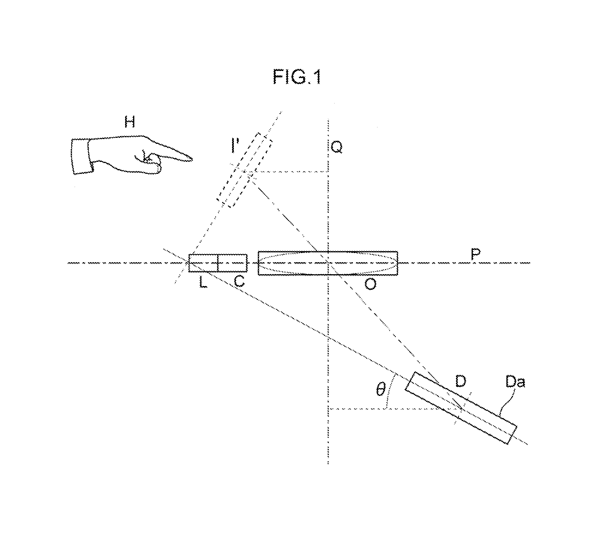
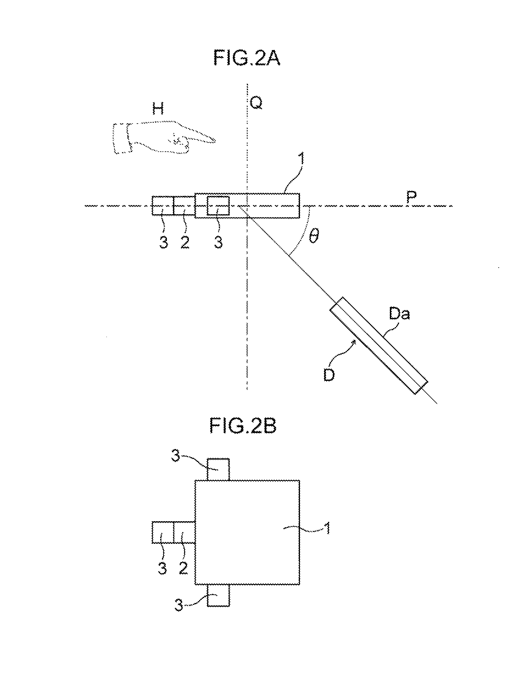
[0039]Next, a more specific embodiment of the user interface display device according to the present invention will be described. FIG. 2A is a schematic view showing a configuration of the user interface display device according to a FIG. 2B is a plan view around an optical panel 1 of this user interface display device.

[0040]In the user interface display device according to this embodiment, two plano-convex Fresnel lenses (an outside shape of 170 mm square, and a focal length of 305 mm) laid one on top of the other are used as the optical panel 1. A ¼-inch CMOS camera (NCM03-S manufactured by Asahi Electronics Laboratory Co., Ltd.) is used as a camera 2. Infrared LEDs (having a wavelength of 850 nm, and an output of 8 mW; LED851W manufactured by Thorlabs, Inc.) are used as light sources 3. A liquid crystal display (a 12-inch TFT display manufactured by Panasonic Corporation) is used as the flat panel display D.

[0041]Although not shown, a computer is provided in the aforementioned u...

second embodiment

[0050]Next, the user interface display device according to the present invention will be described.

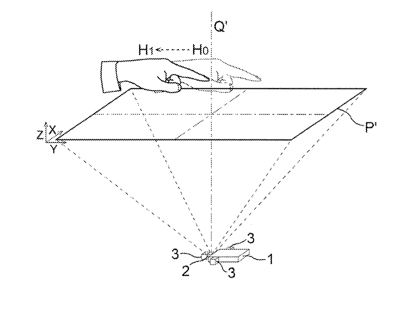
[0051]FIGS. 6, 10 and 11 are views showing configurations of the user interface display device according to the second embodiment of the present invention. FIG. 7 is a view illustrating a method for projecting the spatial image I′ in this user interface display device. In the figures, a plane P indicated by a dash-dot line is a “virtual horizontal plane” (“element plane” in an optical element) based on the sensibility of an operator, as in the aforementioned first embodiment, and planes P′ and P″ indicated by dash-dot lines are “virtual imaging planes” corresponding to the virtual imaging plane P′ (with reference to FIGS. 3 to 5) formed by the camera 2 of the first embodiment.

[0052]The user interface display device according to the present embodiment uses an optical panel (micromirror array 10) having an image-forming function to cause a video picture (image I) appearing on the display...

third embodiment

[0063]Next, the user interface display device according to the present invention will be described.

[0064]FIG. 12 is a view showing a configuration of the user interface display device according to the third embodiment of the present invention. FIGS. 13, 15, 17 and 19 are perspective views of micromirror arrays (20, 30, 40 and 50) used in this user interface display device. In the figures, a plane P indicated by a dash-dot line is a “virtual horizontal plane” (“element plane” in an optical element) based on the sensibility of an operator, as in the first and second embodiments, and a plane P′ indicated by a dash-dot line is a “virtual imaging plane” corresponding to the virtual imaging plane P′ (with reference to FIGS. 3 to 5) formed by the camera 2 of the first embodiment and the PSD (4) of the second embodiment.

[0065]The user interface display device according to the present embodiment uses an optical panel (micromirror arrays 20, 30, 40 and 50) having an image-forming function to ...


PUM


Abstract

An optical panel having an image-forming function is disposed in parallel with a virtual horizontal plane so that the optical axis thereof is orthogonal to the virtual horizontal plane. A flat panel display is disposed in offset relation below the optical panel such that a display surface of the flat panel display is inclined at a predetermined angle with respect to the virtual horizontal plane and faces upward. A light source for projecting light toward a hand, and a camera for imaging the reflection of the light from the hand are provided below or above a spatial image image-formed above the optical panel. This provides a user interface display device which does not include structure serving as an obstacle to manipulation around the spatial image projected in space to achieve an interaction with the spatial image by using the hand of the operator in a natural manner.

Description

TECHNICAL FIELD[0001]The present invention relates to a user interface display device which changes a spatial image in bidirectional relation to the motion of a hand (interactively) by moving the hand disposed around the spatial image.BACKGROUND ART[0002]Known schemes for displaying video pictures in space include a two-eye scheme, a multi-eye scheme, a spatial image scheme, a volume display scheme, a hologram scheme and the like. In recent years, there has been proposed a display device for displaying video pictures which allows a user to intuitively manipulate a two-dimensional video picture or a three-dimensional video picture (a spatial image) displayed in space with his or her hand, finger and the like, thereby achieving an interaction with the spatial image.[0003]As a recognition input means (user interface) for a hand, finger and the like in such a display device, there has been proposed a system which forms a lattice of vertical and horizontal light beams in a sensing region...

Claims


Application Information

Patent Timeline
Patent Type & Authority Applications(United States)
IPC IPC(8): G06F3/03G06F3/01G06K9/00
CPCG06F3/0304G06K9/00355G06F3/017G06F3/0425G06T2207/30121G06T7/292G06T7/194G06T7/136G06V40/28
Inventor JUNI, NORIYUKI
Owner NITTO DENKO CORP
Why Eureka
Try Eureka