
Display screen, electronic device and information processing method for the electronic device

Active Publication Date: 2014-08-28
LENOVO SOFTWARE +1
View PDF13 Cites 28 Cited by
  • Summary
  • Abstract
  • Description
  • Claims
  • Application Information

AI Technical Summary

Benefits of technology

The patent text describes a display device and electronic device that can adjust the contrast of a display screen based on the ambient light and the user's behavior. This allows for better adjustment of the displayed parameter value, which can improve the user's experience and meet their needs more effectively.

Problems solved by technology

In the prior arts, because there are ambient light in environment where the display unit are used and the display unit will reflect the ambient light, there is a technical problem that the ambient light causes interference with the displayed contents in the display unit.
However, due to the design of OLED structure itself, its metal cathode has a very large reflectivity.
Thus, the OLED display will strongly reflect the ambient light, and then the display effect is not satisfactory.
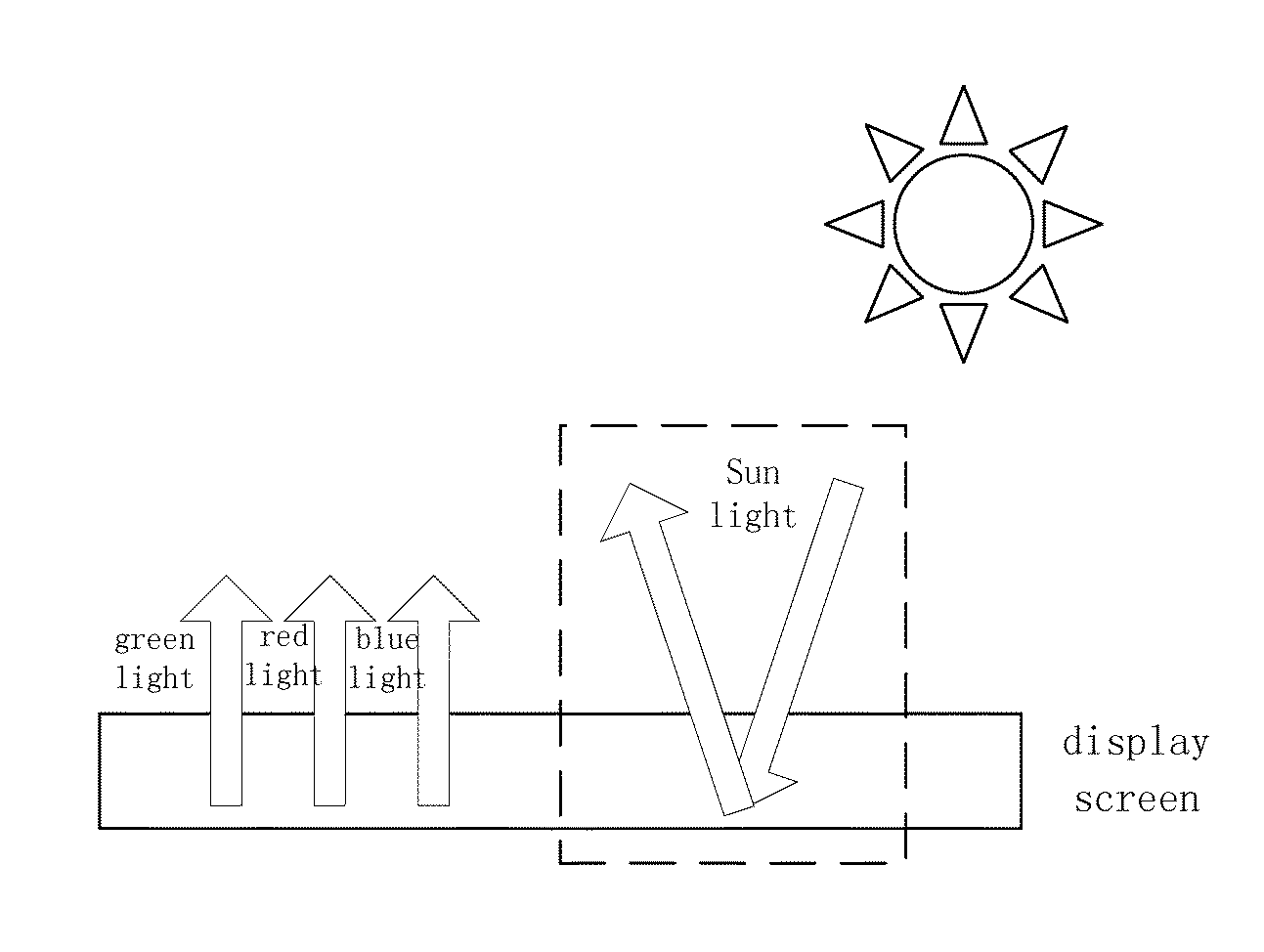
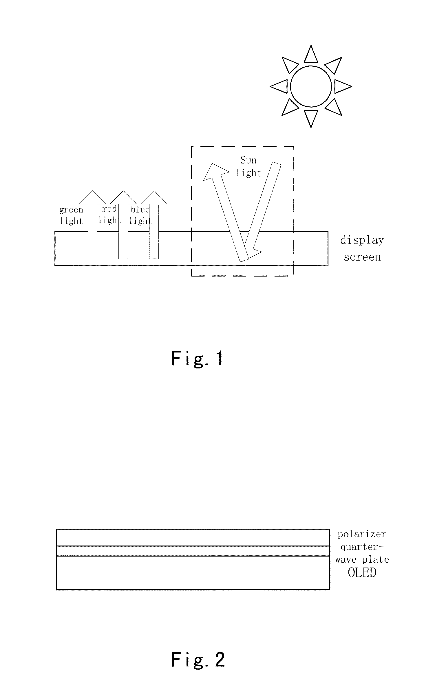
As shown in FIG. 1, when outside ambient light is incident on it, the reflection of the outside ambient light would reduce the contrast of the display screen, thereby resulting in a poor user experience.
As a result, there is a technical problem that the display light source can only be provided on basis of the light source layer for displaying image information, but cannot be provided on basis of the ambient light for displaying image information.
As a result, with respect to the ambient light having different wavelengths, the rotated angles of the optical phases are not consistent with each other.
Further, one technical problem, i.e. a poor effect of blocking reflection of the ambient light having a part of the above described wavelengths, occurs.
Presently, any effective methods to inhibit the disturbance of the ambient light for such display screen have not been proposed.

Method used


Image

  • Display screen, electronic device and information processing method for the electronic device
  • Display screen, electronic device and information processing method for the electronic device
  • Display screen, electronic device and information processing method for the electronic device

Examples


first embodiment

[0132]One embodiment of the present invention provides a display screen, which is not only applicable in a separate display apparatus, but also in an electronic device having an image outputting unit.

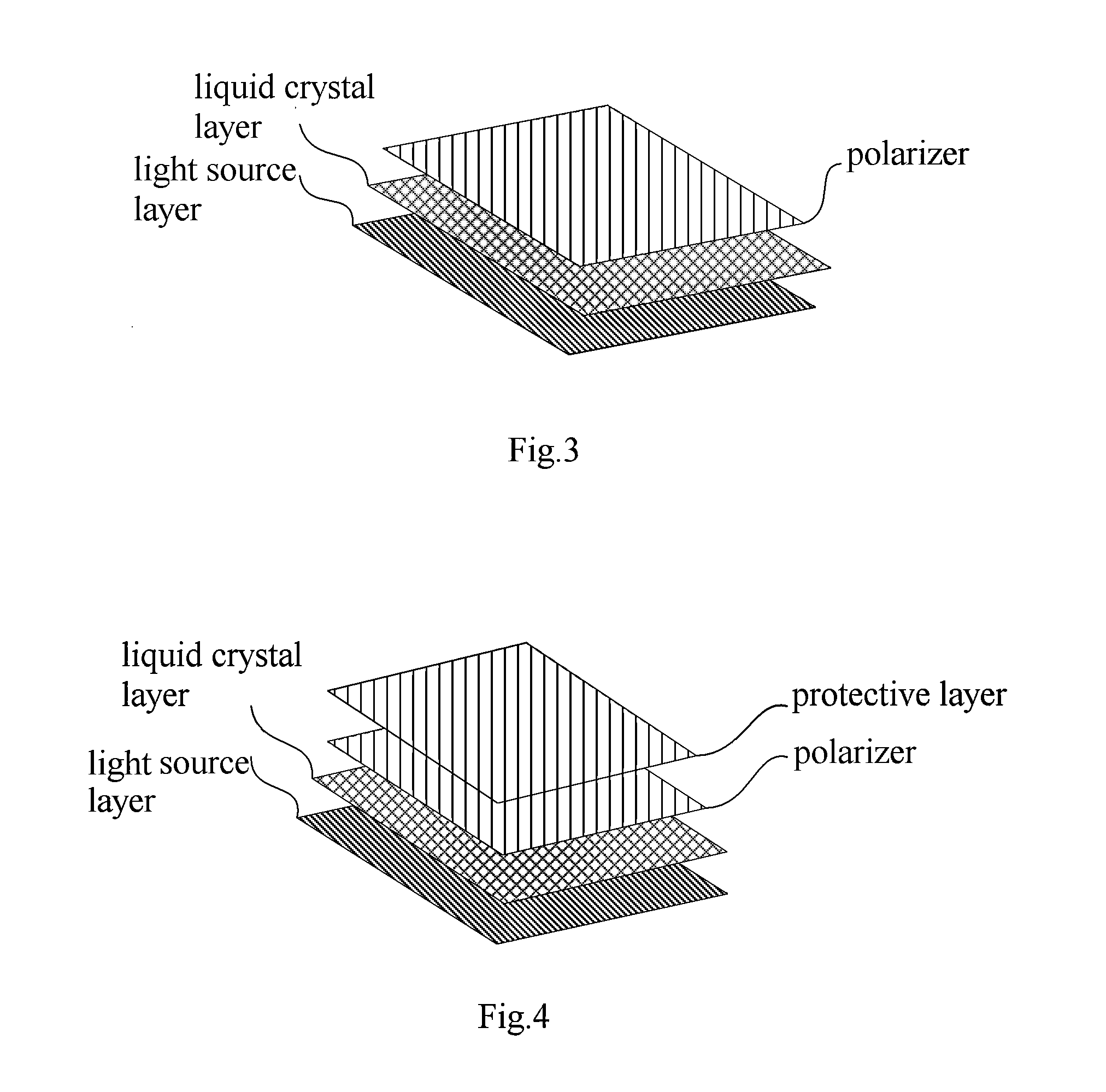
[0133]As shown in FIG. 3, the display screen includes as follows:

[0134]a light source layer, configured to be in an “on” state for providing a display light source corresponding to a first display mode, when the display screen is in the first display mode, and to be in an “off” state when the display screen is in a second display mode different from the first display mode;

[0135]a liquid crystal layer, disposed in front of the light source layer;

[0136]a polarizer, disposed in front of the liquid crystal layer;

[0137]a control unit (not shown), in connection with the liquid crystal layer and configured to control the liquid crystal layer;

[0138]wherein when the display screen is in the first display mode, the liquid crystal layer is controlled by the control unit so that optical phase of po...

second embodiment

[0141]In an embodiment, the display screen further includes a protective layer, disposed in front of the polarizer (above the polarizer in FIG. 4). With reference to FIG. 4, such protective layer is used to protect the polarizer. As one embodiment, the protective layer is made of materials having high transparency, to ensure the displaying effect.

[0142]During the specific embodiment, the light source layer can be OLED, having self luminous characteristic. OLED is structurally composed of a substrate, an anode, a conductive layer, an emitting layer and a metal cathode in order. But since the metal cathode formed on an upper layer of the OLED has a very high reflectivity, it will strongly reflect the ambient light. Although the OLED light source layer is used as an example to make an explanation in the above embodiment of the present invention, the present invention is not limited to this, for example, the light source layer can also be DMS.

[0143]Further, in order to solve the technic...

third embodiment

[0168]The present embodiment discloses a display device, applicable to the electronic device. As shown in FIG. 8, the display device includes a display screen 101 switchable between the transmittance mode and the reflection mode, an electronically controllable phase retarder 102, a polarizer 103 and a control module 104; wherein

[0169]the display screen 101 switchable between the transmittance mode and the reflection mode is used to display in a transmittance mode or a reflection mode;

[0170]the electronically controllable phase retarder 102 is located on the display screen 101 switchable between the transmittance mode and the reflection mode, and a power terminal thereof is provided to be connected with a power supply;

[0171]the polarizer 103 is located on the electronically controllable phase retarder 102;

[0172]the control module 104 respectively is connected with the display screen 101 switchable between the transmittance mode and the reflection mode, and the electronically controll...


PUM


Abstract

A display screen is disclosed. The display screen comprises a light source layer, configured to be in an “on” state for providing a display light source corresponding to a first display mode, when the display screen is in the first display mode, and to be in an “off” state when the display screen is in a second display mode different from the first display mode; a liquid crystal layer, disposed in front of the light source layer; a polarizer, disposed in front of the liquid crystal layer; and a control unit, in connection with the liquid crystal layer and configured to control the liquid crystal layer. An electronic device is also disclosed, including the above described display screen and a method for processing information of the electronic device.

Description

CROSS-REFERENCE TO RELATED APPLICATION[0001]This application claims the benefit of Chinese Patent Applications Nos. CN201310060627.1 filed on Feb. 26, 2013, CN201310062206.2 filed on Feb. 27, 2013, and CN201310074794.1 filed on Mar. 8, 2013 in the State Intellectual Property Office of China, the disclosures of which are incorporated herein by reference.BACKGROUND OF THE INVENTION[0002]1. Field of the Invention[0003]The present invention generally relates to a field of electronic technique, in particular to a display screen and an electronic device having the same. In addition, the present invention also relates to an information processing method used for the electronic device.[0004]2. Description of the Related Art[0005]With continuous development in technology, the electronic technique is also rapidly developing. An increasing number of different types of electronic products have emerged, and the customers enjoy various convenience and comfortable life brought by them.[0006]Genera...

Claims


Application Information

Patent Timeline
IPC IPC(8): G09G3/36G02F1/133
CPCG09G3/36G02F1/13306G02F1/1336G02F1/13363G02F2203/62G02F2413/01G09G2320/0626G09G2360/144G02F1/133618G02F1/133626G02F1/133638
Inventor XU, FANGZHANG, ZHENHUASHANG, KEZHONG, LIKE
Owner LENOVO SOFTWARE
Learn More