Ferritic stainless steel

Active Publication Date: 2014-08-28
JFE STEEL CORP
View PDF7 Cites 5 Cited by
  • Summary
  • Abstract
  • Description
  • Claims
  • Application Information

AI Technical Summary

Benefits of technology

[0022]According to the present invention, it is possible to provide ferritic stainless steel having thermal fatigue resistance, high temperature fatigue resistance, and oxidation resistance equivalent to or more than those of Nb—Si added

Problems solved by technology

However, in the case of the technique according to Patent Literature 1, since Cu is added, continuous oxidation resistance is unsatisfactory, and since Ti is added, the adhesiveness of oxide scale is lowered.
When continuous oxidation resistance is insufficient, the amount of oxide scale is increased during operation at a high temperature, which results in a decrease in the thickness of the base material, excellent thermal fatigue resi

Method used


Image

  • Ferritic stainless steel
  • Ferritic stainless steel
  • Ferritic stainless steel

Examples


example 1

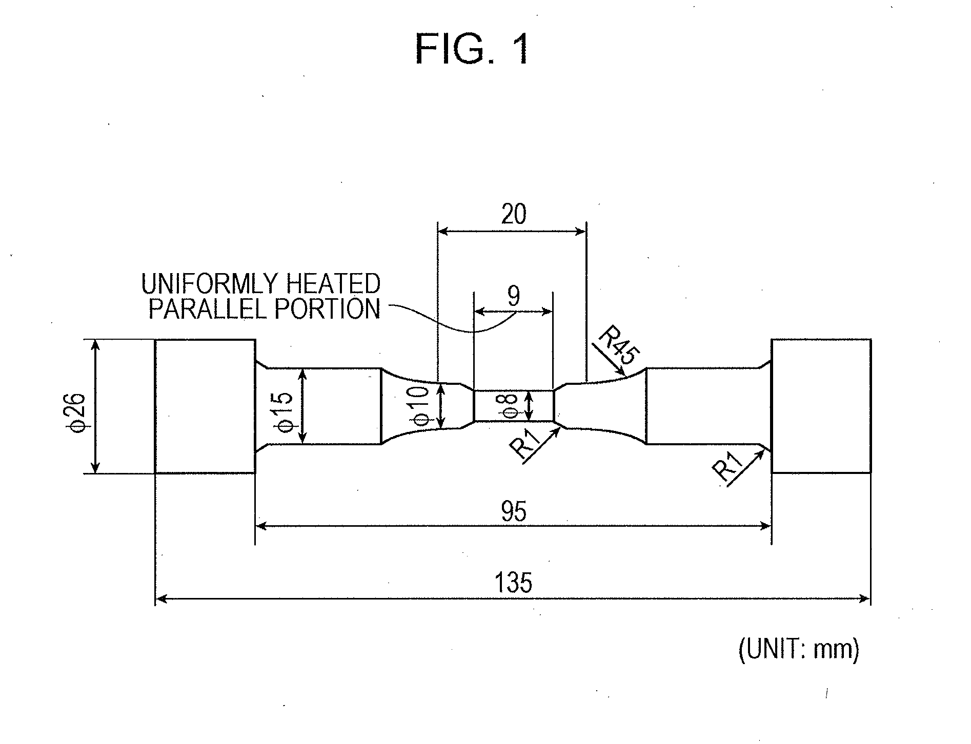
[0104]Steels Nos. 1 to 23 and 27 to 40 having the chemical compositions given in Table 1 were smelted using a vacuum melting furnace, and made into ingots of 30 kg by performing casting. The ingot was made into a sheet bar having a thickness of 35 mm and a width of 150 mm by performing heating up to a temperature of 1170° C. and by performing hot rolling. This sheet bar was divided into two pieces, and one of the two pieces was made into a square bar having a cross section of 30 mm×30 mm by performing forging. The square bar was made into a thermal fatigue test specimen having the dimensions illustrated in FIG. 1 by performing annealing at a temperature in a range from 850° C. to 1050° C. and by performing machining and was then used in a thermal fatigue test described below. An annealing temperature was controlled to be a certain temperature in the range described above depending on a chemical composition, with confirming a microstructure. An annealing temperature described below w...


PUM

PropertyMeasurementUnit
Fractionaaaaaaaaaa
Fractionaaaaaaaaaa
Fractionaaaaaaaaaa

Abstract

Provided is a ferritic stainless steel excellent in terms of thermal fatigue resistance, high-temperature fatigue resistance and oxidation resistance without adding Mo or W, which is an expensive chemical element and with controlling Nb content to be as small as possible. The chemical composition contains, by mass %, C: 0.020% or less, Si: 3.0% or less, Mn: 3.0% or less, P: 0.040% or less, S: 0.030% or less, Cr: 10% to 25%, N: 0.020% or less, Nb: 0.005% to 0.15%, Al: 0.20% to 3.0%, Ti: 5×(C %+N %) to 0.5%, Mo: 0.1% or less, W: 0.1% or less, Cu: 0.55% to 2.0%, B: 0.0002% to 0.0050%, Ni: 0.05% to 1.0%, and the balance being Fe and inevitable impurities, where C % and N % in the expression 5×(C %+N %) respectively represent the contents (mass %) of the chemical elements C and N.

Description

CROSS REFERENCE TO RELATED APPLICATIONS[0001]This is the U.S. National Phase application of PCT International Application No. PCT / JP2012 / 006524, filed Oct. 11, 2012, and claims priority to Japanese Patent Application No. 2011-226505, filed Oct. 14, 2011 and JP 2012-210443, filed Sep. 25, 2012, the disclosures of each of these applications being incorporated herein by reference in their entireties for all purposes.FIELD OF THE INVENTION[0002]The present invention relates to ferritic stainless steel which can be preferably used for the parts of an exhaust system, which are used in a high-temperature environment, such as an exhaust pipe and a catalyst outer cylinder (also called converter case) of an automobile or a motorcycle and an exhaust air duct of a thermal electric power plant.BACKGROUND OF THE INVENTION[0003]The parts of an exhaust system such as an exhaust manifold, an exhaust pipe, a converter case, and a muffler which are used in the environment of the exhaust system of an a...

Claims


Application Information

Patent Timeline
IPC IPC(8): C22C38/54C22C38/52C22C38/50C22C38/48C22C38/00C22C38/44C22C38/42C22C38/06C22C38/04C22C38/02C22C38/34C22C38/46
CPCC22C38/54C22C38/34C22C38/52C22C38/50C22C38/48C22C38/46C22C38/44C22C38/42C22C38/06C22C38/04C22C38/02C22C38/005C22C38/004C22C38/002C22C38/001C22C38/00C21D6/002C21D8/0226C21D8/0236C21D8/0273C21D9/46C22C38/58
Inventor NAKAMURA, TETSUYUKIOTA, HIROKIOGATA, HIROYUKI
Owner JFE STEEL CORP
Why Eureka
Try Eureka