Centralized fresh air cooling system

a fresh air cooling and centralized technology, applied in ventilation systems, lighting and heating apparatus, heating types, etc., can solve the problems of system not working with forced air units to achieve energy savings, waste of electricity, etc., and achieve the effect of reducing the total tim

Active Publication Date: 2014-08-28
RICHARDS MIKE
View PDF2 Cites 11 Cited by
  • Summary
  • Abstract
  • Description
  • Claims
  • Application Information

AI Technical Summary

Benefits of technology

[0014]It is an object of the centralized fresh air cooling system to reduce the total time that an air conditioning system needs to run to provide the same comfort all day. This is accomplished by automatically altering the air flow from the air outlet vents to the attic. When the outside ai

Problems solved by technology

This results in a waste of electricity.
While these patents disclose an air circulation system that venti

Method used


Image

  • Centralized fresh air cooling system
  • Centralized fresh air cooling system
  • Centralized fresh air cooling system

Examples


Embodiment Construction

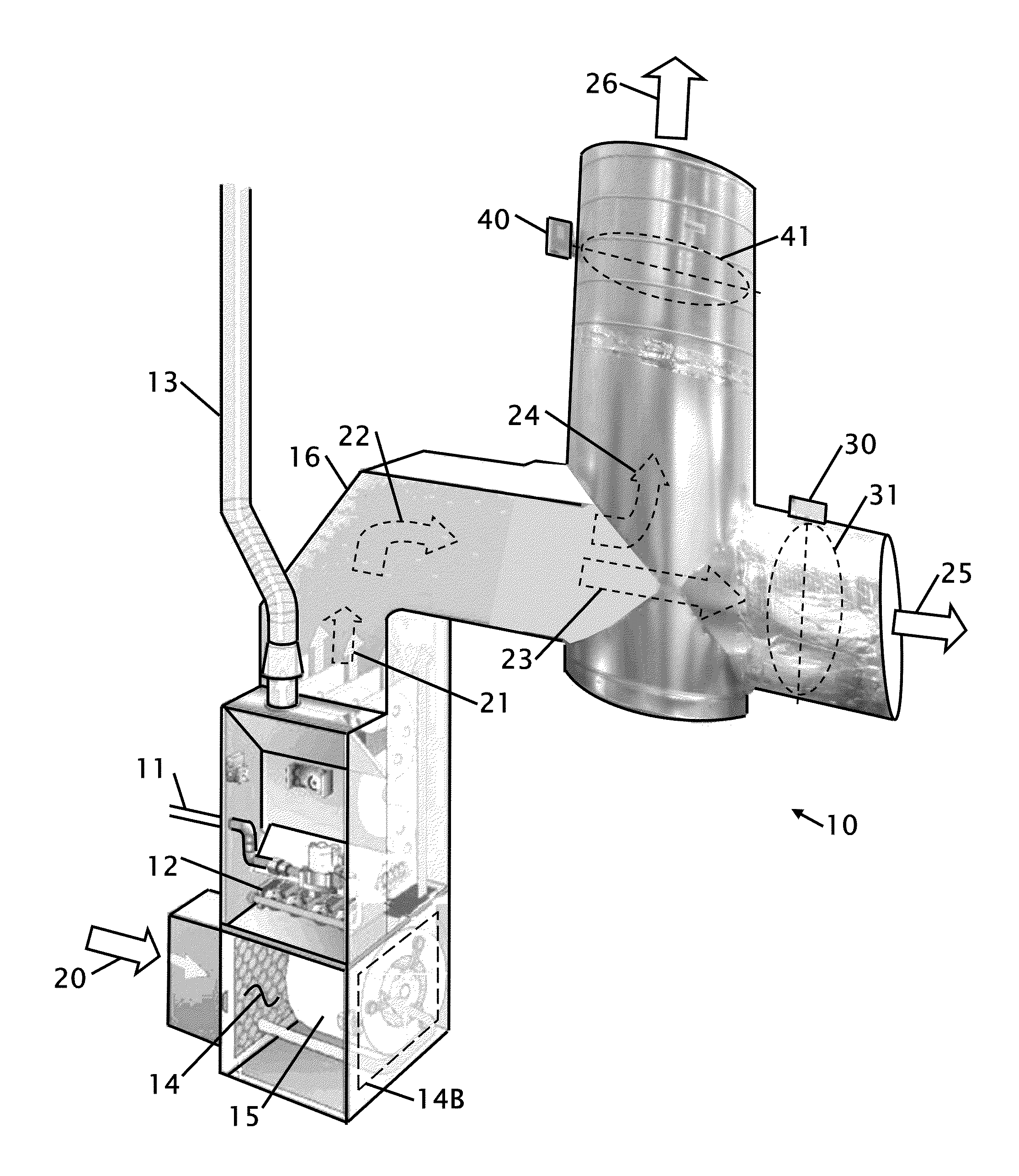
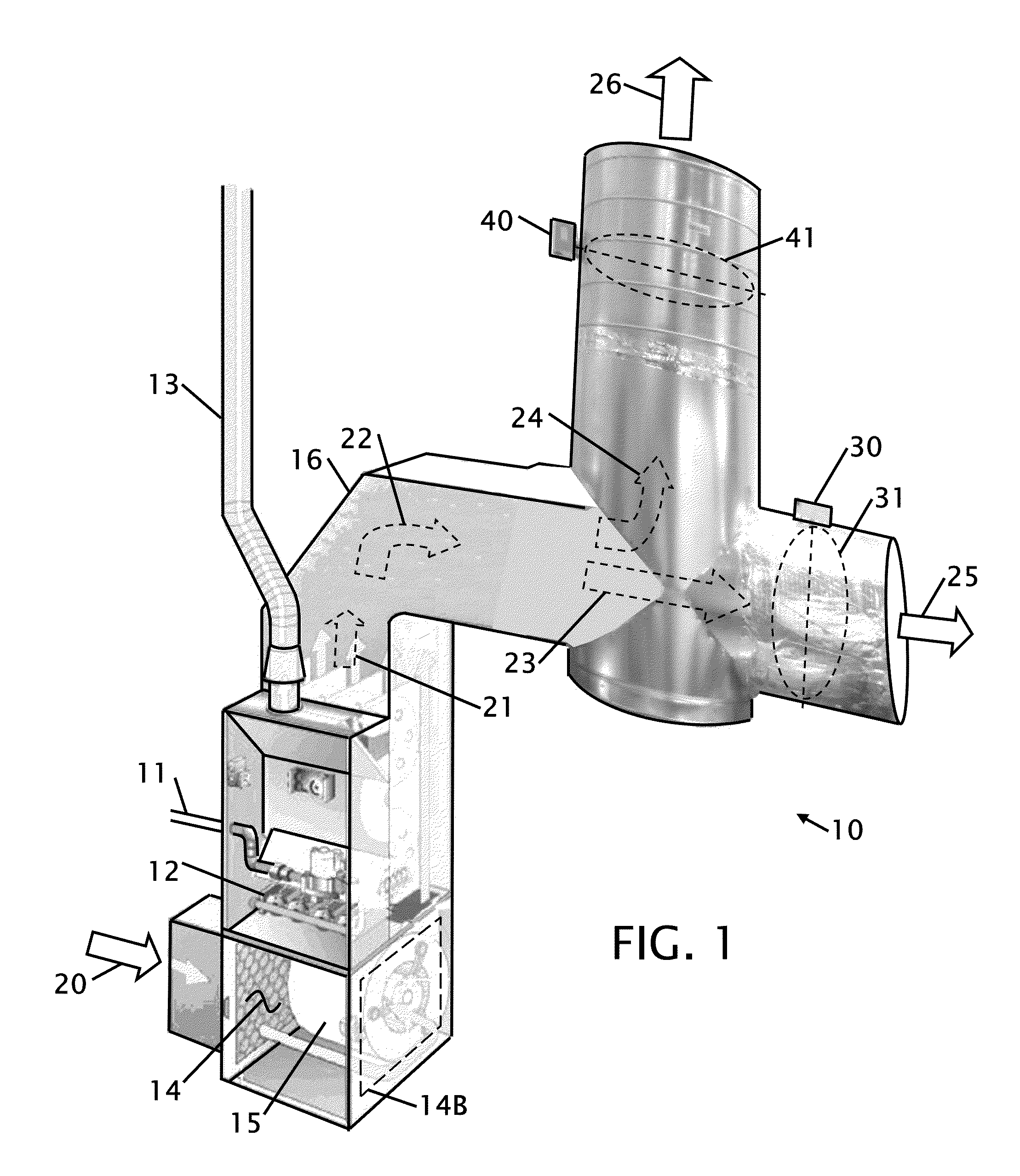
[0025]FIG. 1 shows a perspective view of a forced air unit with the directional diverter installed 10. The embodiment shown, provides one contemplated arrangement of the components, but other orientations and configurations are contemplated that would provide equivalent functions. The basic forced air unit is unchanged where air 20 enters into the forced air unit, a gas line 11 provides a fuel source for a combustion heater 12 to warm air 21 that is recirculated 25 back into a house or building. Exhaust pipe 13 vents burned fuel to outside of the residence or building.

[0026]The installation of the fresh air cooling system requires a diverter to be added after the forced air unit and the control unit is replaced. In the preferred embodiment, air 20 is drawn into the forced air unit from the return(s) of the house or building. A filter 14 cleans the air to prevent combustible material from entering the forced air unit where it can be a fire hazard or blow dirt through the forced air u...


PUM


Abstract

A centralized fresh air cooling system that operates with outside air that vents inside house air into the attic of a house or building. A damper redirects air from the output of the central air circulator to the attic area to blow the hot attic air out of an attic. A typical central air circulator can replace the air within a house or building five to ten times an hour. They system can be retrofit to most central air systems by replacing the thermostats and installing the damper between the air circulator and the house or building ducting. Outside cooler air is drawn in windows or other openings in house or building, into the air circulator returns and then into the attic. The system uses multiple sensors and control mechanism to ensure optimal energy savings.

Description

CROSS REFERENCE TO RELATED APPLICATIONS[0001]Not ApplicableSTATEMENT REGARDING FEDERALLY SPONSORED RESEARCH OR DEVELOPMENT[0002]Not ApplicableTHE NAMES OF THE PARTIES TO A JOINT RESEARCH AGREEMENT[0003]Not ApplicableINCORPORATION-BY-REFERENCE OF MATERIAL SUBMITTED ON A COMPACT DISC[0004]Not ApplicableBACKGROUND OF THE INVENTION[0005]1. Field of the invention[0006]This invention relates to improvements and energy savings in house cooling.[0007]More particularly, the present house cooling system uses an existing forced air unit to draw air into the furnace return and exhaust the air into the attic to draw cold air into a house, remove hot air from within the house and push hot air out of the attic. The system uses one or more dampers to redirect the air to the house ducts or the attic.[0008]2. Description of Related Art including information disclosed under 37 CFR 1.97 and 1.98.[0009]Most houses use either an air conditioning system to cool a house, or attic fan that draws air in from...

Claims


Application Information

Patent Timeline
IPC IPC(8): F24F7/04
CPCF24F7/04F24F11/0001F24F2011/0006
Inventor RICHARDS, MIKE
Owner RICHARDS MIKE
Why Eureka
Try Eureka