
Device for projecting an image into a display area, having a screen for displaying an intermediate image

a technology for projecting images and display areas, applied in the direction of projectors, instruments, optics, etc., can solve the problems of insufficient etendue of imagers, inability to arbitrarily large components of devices, limited space available for devices,

Active Publication Date: 2014-09-04
JABIL OPTICS GERMANY GMBH
View PDF17 Cites 32 Cited by
  • Summary
  • Abstract
  • Description
  • Claims
  • Application Information

AI Technical Summary

Benefits of technology

The invention is a device that can project an image onto a screen more efficiently, making it brighter. The device is designed to emit the image into the screen with maximum intensity, increasing the overall projection efficiency. The screen is tilted to prevent reflections and can be used to fold the optical path of the device, making it more compact. The screen can be formed as an ellipsoid segment with two focal points, one of which is in the exit pupil of the first projecting device and the other in the pupil of the second projecting device.

Problems solved by technology

Since the installation space available for the device is limited, especially in motor vehicles, but also in other applications, the components of the device cannot be arbitrarily large.
Particularly, the employed imager, such as a DMD (Digital Micro-mirror Device with arrayed micro-mirror actuators, wherein the micro-mirrors move for rendering the image) or an LCoS (Liquid Crystal on Silicon, liquid crystals on a silicon substrate) are so small that the etendue of the imager is insufficient to fill the etendue of a projection device that projects the image directly from the imager to the display area.

Method used


Image

  • Device for projecting an image into a display area, having a screen for displaying an intermediate image
  • Device for projecting an image into a display area, having a screen for displaying an intermediate image
  • Device for projecting an image into a display area, having a screen for displaying an intermediate image

Examples


Embodiment Construction

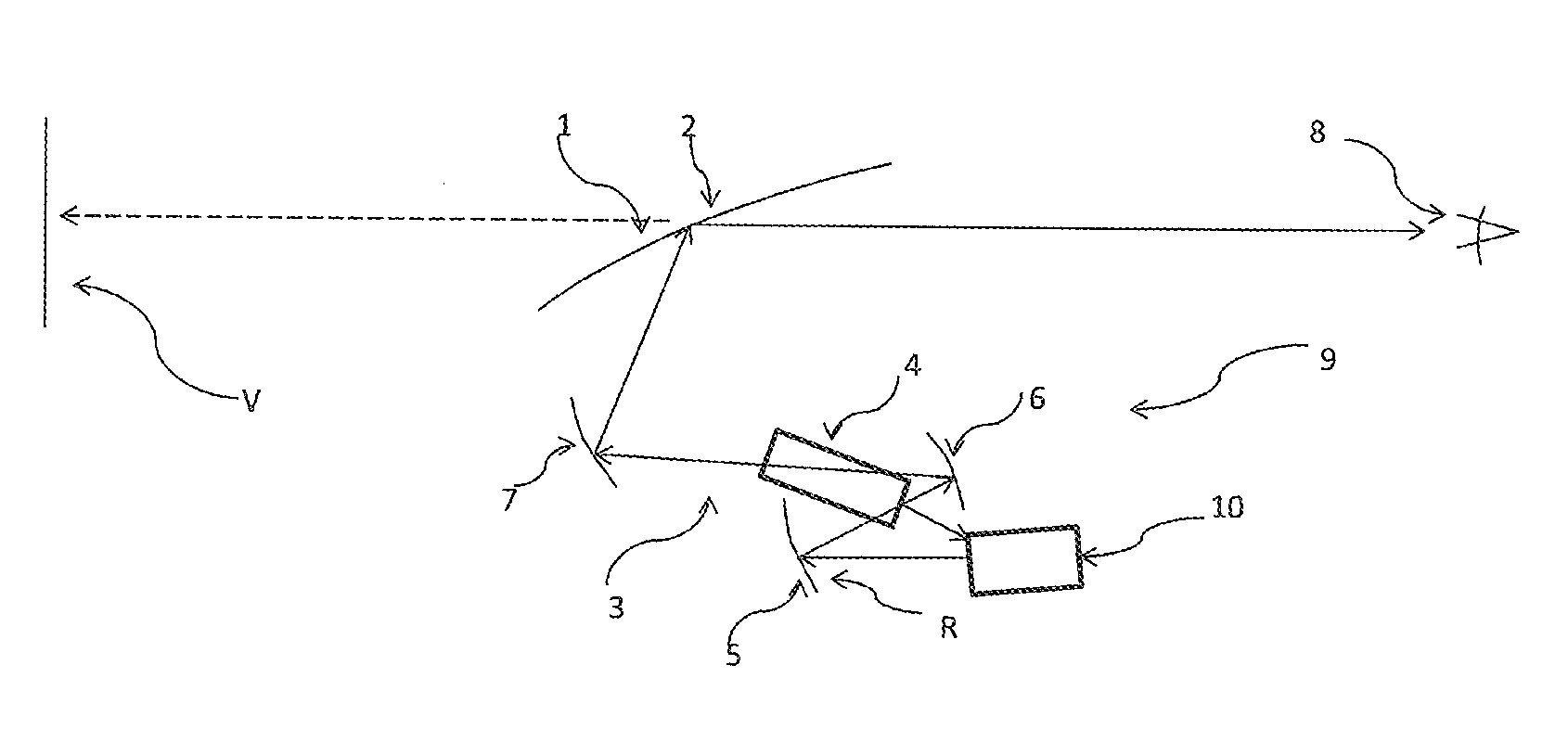
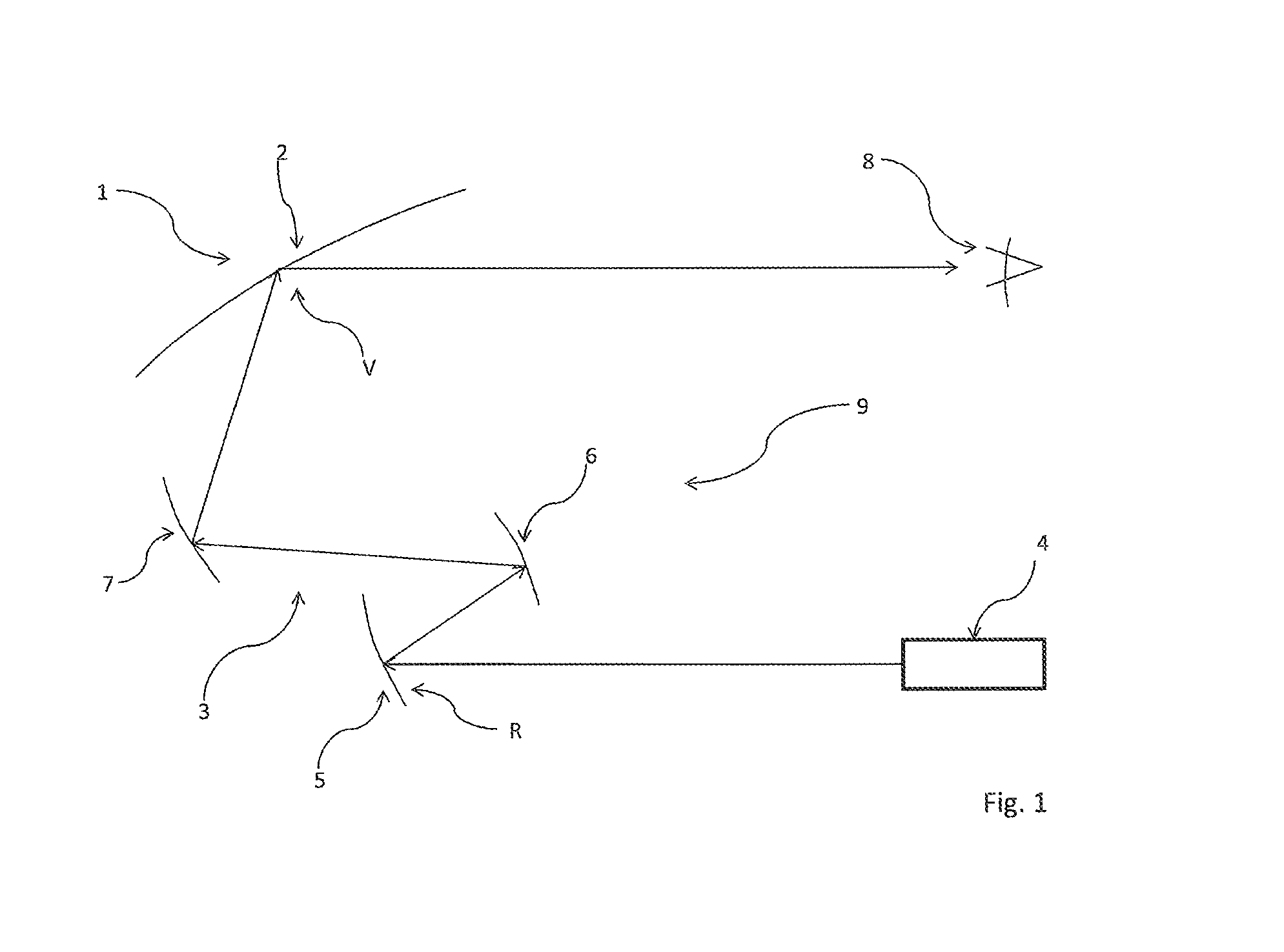
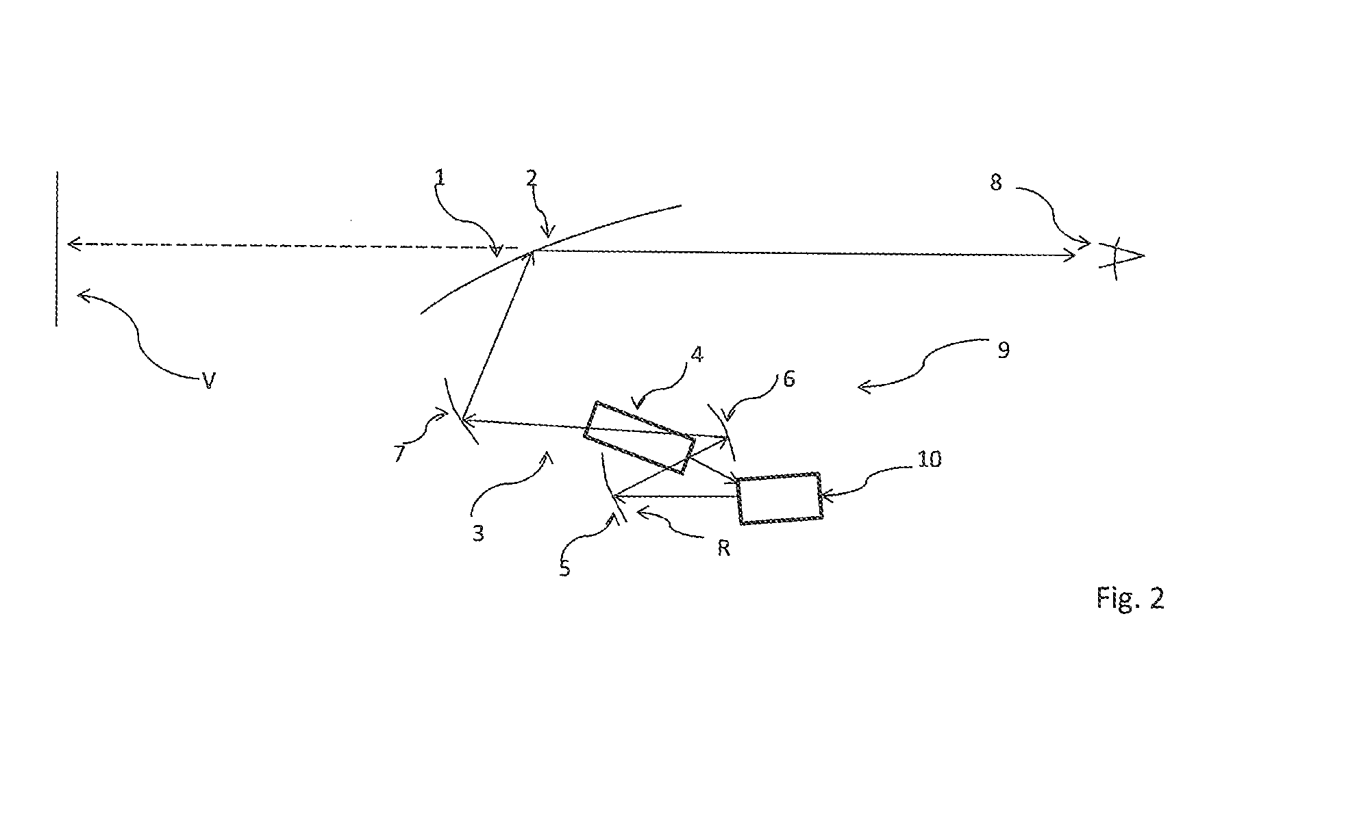
[0029]First, the structure and function of a device according to the invention will be described with reference to the exemplary embodiment of FIG. 1.

[0030]The device 1 for projecting an image in a display area 2 is shown with a projection beam path 3 illustrated by arrows. Along the projection beam path 3, the image of an imager is projected into the display area 2. The projection beam path 3 extends from a projector 4 to a screen 5, from the screen 5 to a first mirror 6, and from there to a second mirror 7, and from the second mirror 7 to the display area 2 The image projected into the display area 2 can be seen by an observer 8, wherein the image in the display area 2 can be a real or a virtual image.

[0031]The projector 4 may include the image-forming imager and a first projection device projecting the image from the imager onto the screen 5. The screen 5 is provided to enlarge the etendue of the projector 4, wherein the screen 5 can be for example a reflective or a transmissive ...


PUM


Abstract

Device (1) for projecting an image into a display area (2), with an imager (31) generating the picture, a first projection device (30) for generating a real intermediate image (R), a screen (5) onto which the first projection device (32) projects the intermediate image (R) and to a second projection device (9) projecting the intermediate image (R) into the display area (2). In order to project the image with the least possible loss of brightness, the invention provides that main beam directions (H, H′, H″) of the screen (5) point into an entrance pupil (20) of the second projection device (9).

Description

CROSS-REFERENCE TO RELATED PATENT APPLICATIONS[0001]This application claims the benefit of Germany Application 10 2013 203 616.7, filed Mar. 4, 2013 including the specification, drawings, claims and abstract, is incorporated herein by reference in its entirety.BACKGROUND[0002]The disclosure relates to a device for projecting an image in a display area having an imager forming the image, a first projection device for generating a real intermediate image of the image, a screen onto which the first projection device projects the intermediate image, and a second projection device that projects the intermediate image into the display area.STATE OF THE ART[0003]Devices for projecting an image of the aforementioned type are generally known. For example, such a device is part of a so-called head-up which displays to an occupant of a motor vehicle information in the field of view of the occupant. The information is projected into the display area of the device, for example as a virtual image...

Claims


Application Information

Patent Timeline
Patent Type & Authority Applications(United States)
IPC IPC(8): G03B21/14
CPCG03B21/14G03B21/28G02B27/0101G02B27/01G02B27/18
Inventor PIEHLER, DR. EBERHARD
Owner JABIL OPTICS GERMANY GMBH
Learn More