Wall mounting device

a wall mounting and mounting plate technology, applied in the direction of screws, threaded fasteners, applications, etc., can solve the problems of reducing the appearance and value of the room, time-consuming and labor-intensive to repair these holes, and difficulty in visible, so as to reduce the deformation and displacement of the wall, the resistance of the pin from the wall is weak, and the drive is easy.

Inactive Publication Date: 2014-09-04
FUMIO SUDOH
View PDF20 Cites 9 Cited by
  • Summary
  • Abstract
  • Description
  • Claims
  • Application Information

AI Technical Summary

Benefits of technology

[0027]A wall mounting device according to the present invention is equipped with a needle member and a head member with which the needle member is combined so that the needle member is outwardly projected from the head member, the needle member being driven into a wall so that the head member is mounted on the wall, wherein the needle member is equipped with at least one elongate plate-shaped pin with a pointed end section. As a result, the driving force that is received when the pin is driven into a wall is concentrated at the end section, allowing the pin to be easily driven into hard walls. More specifically, the plate-shaped pin has a thin, narrow, plate-shaped cross-section so that deformation and displacement of the wall is minimized when the pin is driven in, unlike when driving a pin with a circular cross section and a large diameter is driven into a wall. As a result, the resistance which the pin receives from the wall is weak, making the pin easier to drive in. In addition, the damage to the wall can be reduced as well. After the pin is driven in, the wall supports the plate-shaped pin from both sides, resulting in the wall mounting device being more firmly supported in the wall. Thus, a wall mounting device is provided wherein a needle member can be accurately and reliably driven into any type of wall.
[0028]In addition, when the head member is formed with a support / guide groove that supports the needle member combined with the head member and that guides the movement of the needle member as the needle member, starting from this supported state, is pushed through the head member and driven into a wall, the needle member is guided by the support / guide groove as it is driven into the wall. As a result, the needle member is driven into the wall in a stable and reliable manner while maintaining a correct orientation.
[0029]Furthermore, when the plate-shaped pin extends diagonally from the head member, setting up the plate-shaped pin so that the end of the plate-shaped pin extends diagonally downward when the wall mounting device is driven into the wall, which results in the wall mounting device being drawn tightly against the wall by the weight of an object, e.g., furniture applied to the wall mounting device. As a result, the wall mounting device is prevented from easily slipping out from the wall and the head member is prevented from easily slipping away from the plate-shaped pin.
[0030]Thus, while the specific configuration will be determined according to the material of the wall, the present wall mounting device can be driven into the wall accurately and reliably while maintaining a stable orientation, with failures during the driving operation being minimized.

Problems solved by technology

Such large holes may diminish the appearance and value of the room.
Repairing these holes is time consuming and repairing holes inexpensively and so that they are not visible is extremely difficult.
However, it is difficult to keep the pin driven in while maintaining a proper attitude of the pin to the hard wall with such great force.
If the driving pin itself becomes deformed or the attitude of the pin changes, the driving pin cannot be attached with a correct direction to the wall, leading to drawbacks such as the driving pin tending to fall out from the wall.

Method used


Image

  • Wall mounting device
  • Wall mounting device
  • Wall mounting device

Examples


first embodiment

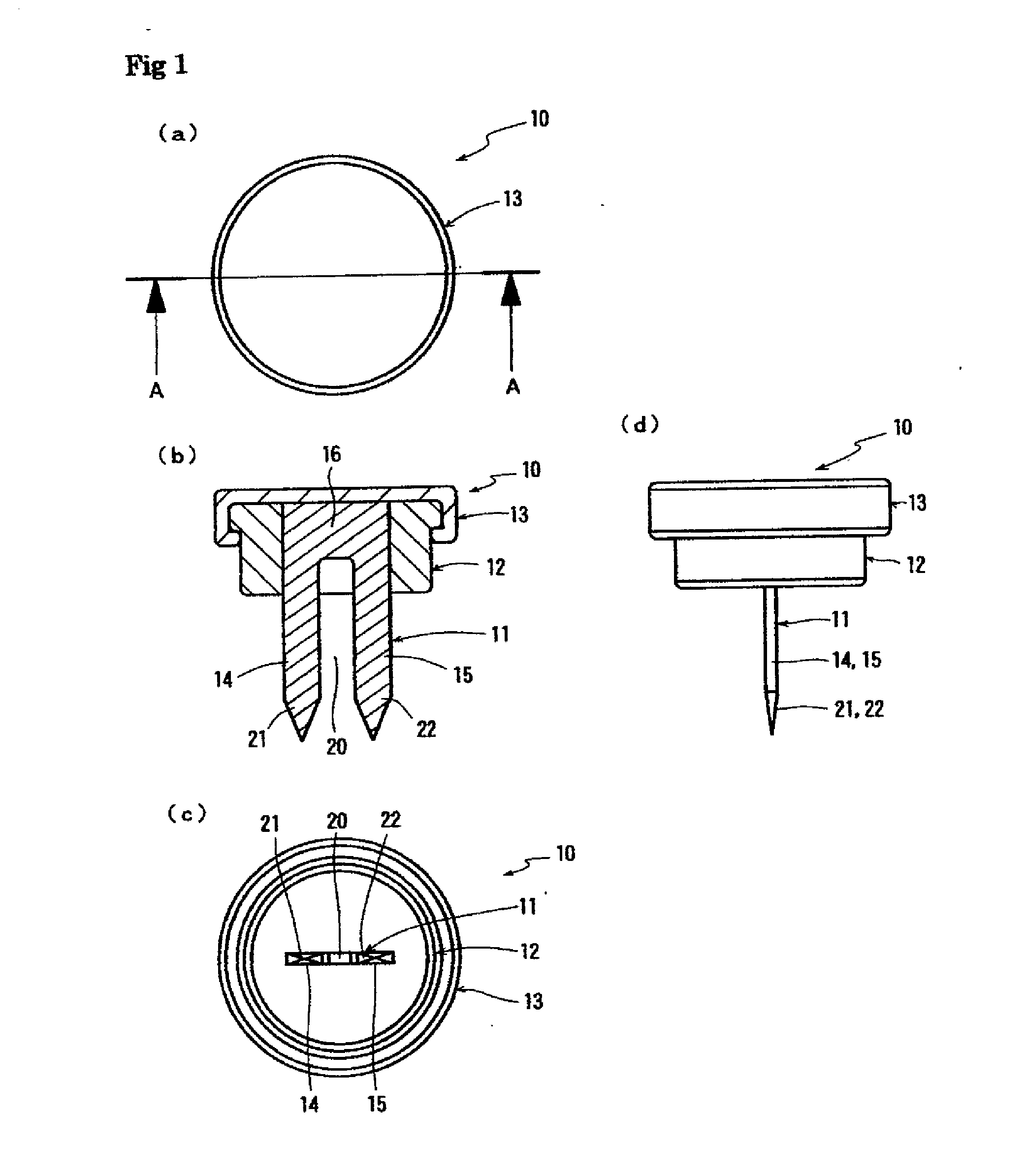
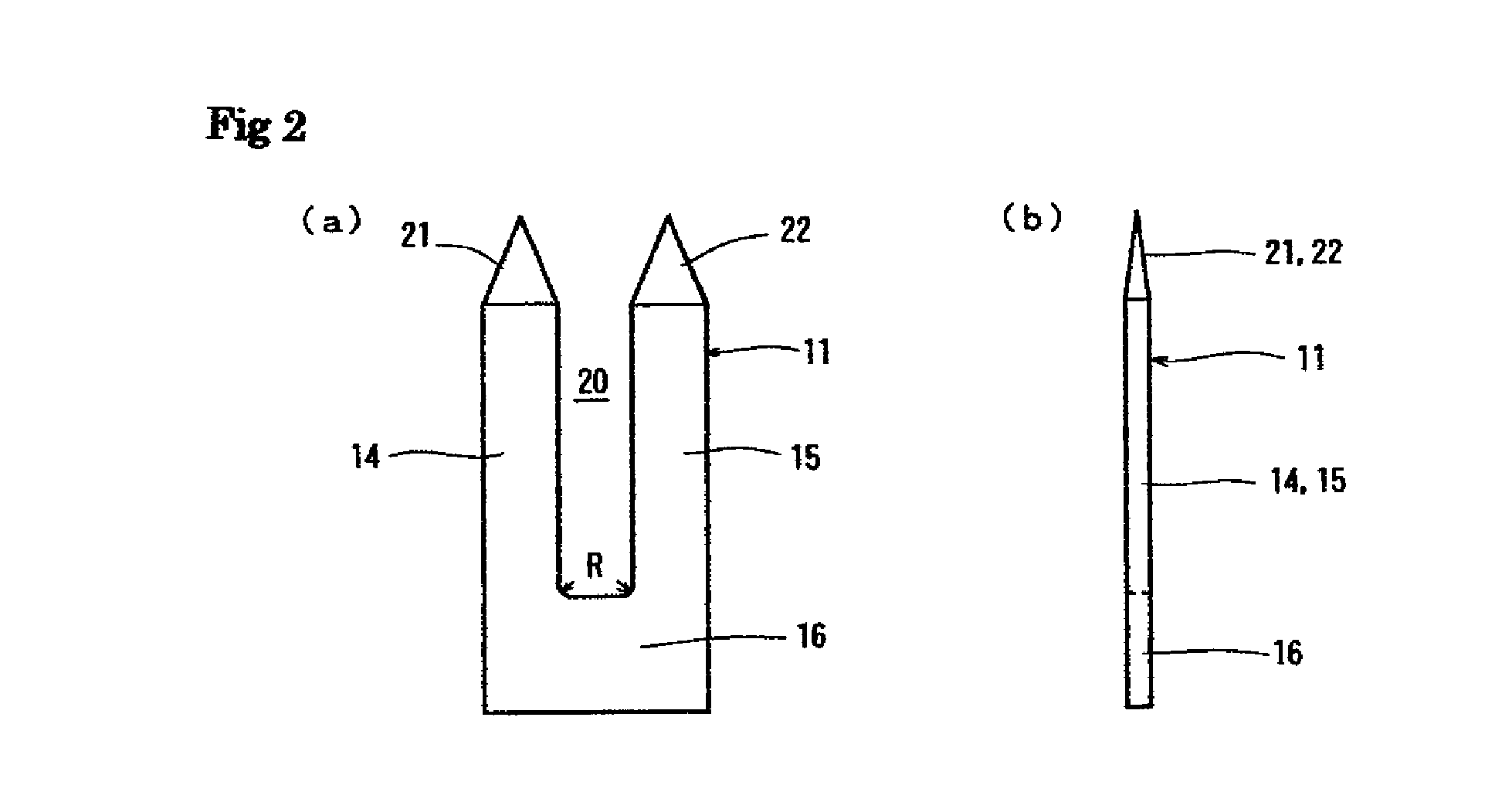
[0053]FIG. 1 to FIG. 4 are drawings showing a first embodiment of a wall mounting device according to the present invention. FIG. 1 (a) is a plan drawing of the wall mounting device. FIG. 1 (b) is a cross-section drawing along the A-A line of the wall mounting device shown in FIG. 1 (a). FIG. 1 (c) is a bottom-view drawing. FIG. 1 (d) is a side-view drawing. FIG. 2 shows a needle member used in the wall mounting device shown in FIG. 1. FIG. 2 (a) is a front-view drawing. FIG. 2 (b) is a side-view drawing. In addition, FIG. 3 shows a head member of the wall mounting device shown in FIG. 1. FIG. 3 (a) is a top-view drawing. FIG. 3 (b) is a cross-section drawing along the B-B line of the head member shown in FIG. 3 (a). FIG. 3 (c) is a bottom-view drawing. Furthermore, FIG. 4 is a drawing showing a cap used in the wall mounting device shown in FIG. 1. FIG. 4 (a) is a top-view drawing. FIG. 4 (b) is a cross-section drawing along the C-C line of the cap shown in FIG. 4 (a). FIG. 4 (c) is...

second embodiment

[0062]FIG. 6 to FIG. 9 show another embodiment of the wall mounting device according to the present invention. FIG. 6 shows a second embodiment of the wall mounting device according to the present invention. FIG. 6 (a) is a vertical cross-section drawing. FIG. 6 (b) is a bottom-view drawing. FIG. 7 shows a needle member used in the wall mounting device shown in FIG. 6. FIG. 7 (a) is a front-view drawing. FIG. 7 (b) is a side-view drawing. FIG. 8 shows a head member used in the wall mounting device shown in FIG. 6. FIG. 8 (a) is a top-view drawing. FIG. 8 (b) is a vertical cross-section drawing along the D-D line at the central position in FIG. 8 (a). FIG. 8 (c) is a bottom-view drawing. FIG. 9 shows a cap used in the wall mounting device shown in FIG. 6. FIG. 9 (a) is a top-view drawing. FIG. 9 (b) is a vertical cross-section drawing along the E-E line at the central position in FIG. 9 (a). FIG. 9 (c) is a bottom-view drawing. In the description of the second embodiment, members and...

third embodiment

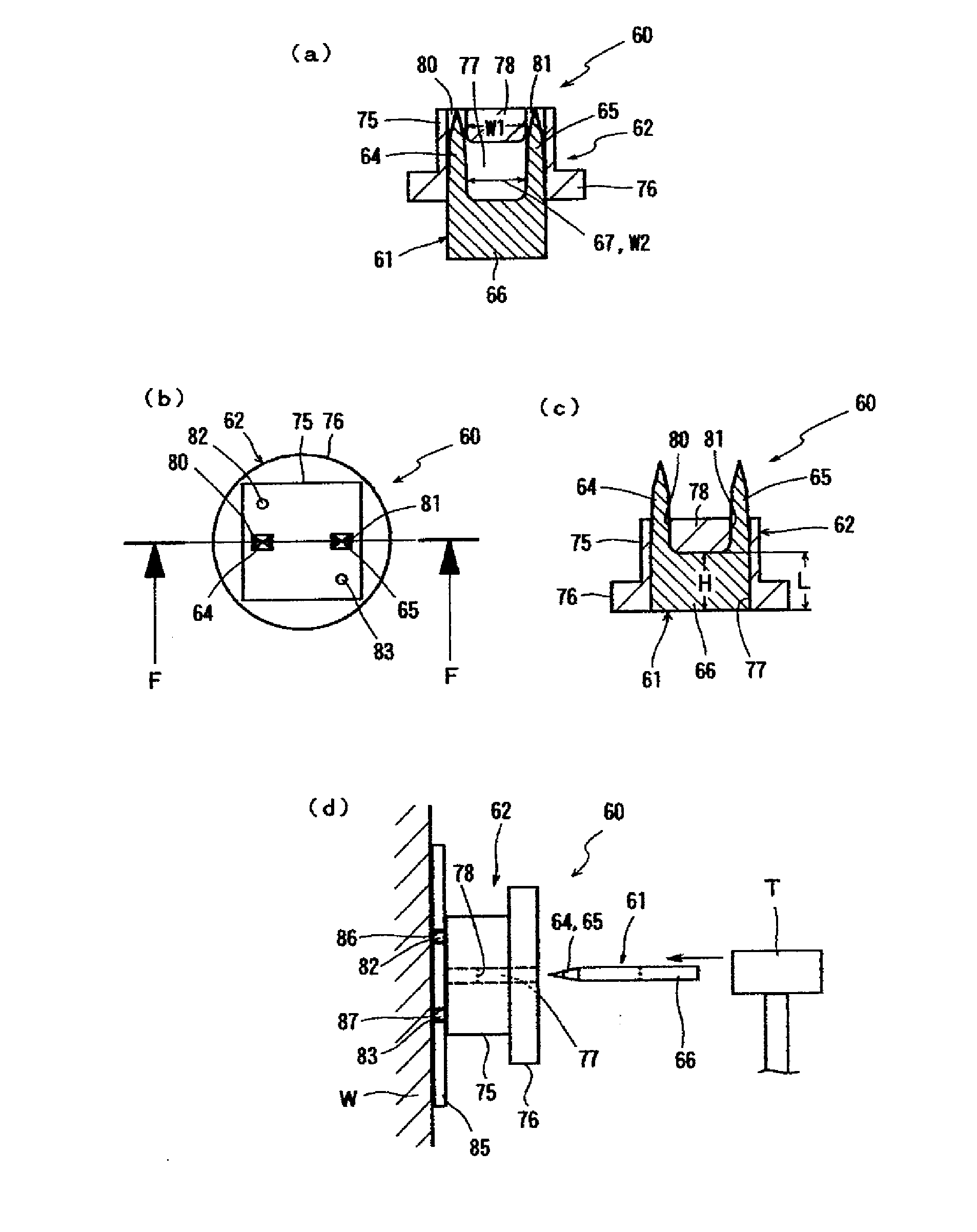
[0069]FIG. 10 shows a third embodiment of the wall mounting device according to the present invention. FIG. 10 (a) is a cross-section drawing of the wall mounting device with a section of the needle member pushed into the slit. FIG. 10 (b) is a plan drawing showing the wall mounting device with the needle member pushed into the slit. FIG. 10 (c) is a cross-section drawing along the F-F line in FIG. 10 (b). FIG. 10 (d) shows the wall mounting device of this embodiment when it is driven into a wall. In the third embodiment shown in FIG. 10 of the wall mounting device according to the present invention, the mounting device 60 is equipped with: a metal needle member 61; and a resin head member 62 with which a needle member 61 is combined by being inserted through the head member 62. The mounting device 60 is equipped with a cap that covers the head member 62 but the description thereof will be omitted since a structure equivalent to that of the cap 13 shown in the first embodiment can b...


PUM


Abstract

The present invention provides a wall mounting device that can be driven accurately and reliably into a wall, even if the wall is a hard wall such as a concrete wall.
The wall mounting device is equipped with a needle member 11 that is driven into a wall and a head member 12 that is thereby mounted to the wall. The needle member 11 is equipped with at least one plate-shaped pin, i.e., elongate plate-shaped pins 14, 15, that includes pointed end sections 21, 22 and is formed relatively thin overall. In the plate-shaped pins 14, 15, the force received when the pins are driven into the wall is concentrated at the end sections 21, 22, thus allowing the pins to be easily driven into the wall. In addition, the pins are formed with thin, narrow, and plate-shaped cross-sections, thus reducing the deformation and dislocation of the wall material when the pins are driven into the wall. As a result, damage to the wall is minimized. After being driven in, the wall supports the plate-shaped pins 14, 15 from both sides, providing firm support for the wall mounting device. The object to be attached to the wall is hung on the wall by being directly engaged with the head member 12 or by being indirectly engaged by way of an engagement piece secured to the head member 12.

Description

TECHNICAL FIELD[0001]The present invention relates to a wall mounting device that is used on walls of buildings such as residences to hook different types of objects, e.g., furniture such as shelves and boxes, devices such as clocks and air conditioners, and decorative items such as paintings and sculptures.BACKGROUND TECHNOLOGY[0002]In standard residences and the like, objects such as shelves and storage cases, and mirrors and picture frames have been attached to walls formed from wood such as veneer panels, plasterboard, concrete, or the like. An example of a structure used to attach objects of this type to walls is a structure wherein a pin is secured to the wall material and the object is hooked onto the secured pin. The object is simply hooked to the pin and the attachment tools or devices do not stick out from the object, therefore this type of hook structure is attractive. Furthermore, the object can be easily removed from the wall by simply unhooking the object from the pin....

Claims


Application Information

Patent Timeline
Patent Type & Authority Applications(United States)
IPC IPC(8): F16B19/00
CPCF16B19/00A47G1/22A47G25/0607F16B15/00F16B15/0015
Inventor NAMEKAWA, TADASHI
Owner FUMIO SUDOH
Why Eureka
Try Eureka