Flexible tank for fluid containerisation

a flexible tank and container technology, applied in the direction of containers, packaging, linings/internal coatings, etc., can solve the problems of excessive pressure on exacerbate the risk of permanent distortion or deformation, structural failure, etc., and achieve the effect of bending the end and side walls of the container permanently outwards

Inactive Publication Date: 2014-09-11
CLIVE SMITH MARTIN +1
View PDF15 Cites 7 Cited by
  • Summary
  • Abstract
  • Description
  • Claims
  • Application Information

AI Technical Summary

Benefits of technology

[0012]In the present invention, a flexible bag or tank is configured for containerisation, that is use within otherwise standard container confines, so that upon fill the tank is supported by container floor, side walls and end structures, but with a top surface clear of the container roof and so accessible to some form of damper, buffer or restraint provision, such as through external bias, loading, baffle or displacement for local re-shaping to help discipline dynamic behaviour of liquid contents under load. The damper or baffle action can be through a top wall or bag skin, from outside and / or within, with inhibition of baffle movement to preserve baffle calming, damping or suppressing action.
[0014]Generally, particular attention is paid to a tank upper regions and a top surface of liquid content, where the more problematic liquid movement behaviour arises, and to mutual interaction with container upper regions to impose discipline. Thus, from operational considerations, a flexible tank bag occupying an entire container internal volumetric capacity would, when filled with liquid, take the loaded container beyond approved weight limitations and make the container unwieldy to handle, let alone lift and stack to be safely supported by other underlying containers without distortion and damage. So in practice a hitherto unused and wasted or dead ‘headspace’ volume (necessarily) arises within container confines above a flexible tank.
[0015]In one aspect of the invention, the Applicant seeks to put to constructive use what would otherwise be such wasted space within a container above a flexible tank, by fitting a buffer or damper to suppress unwanted upper body and surface movement of liquid in a flexible tank.
[0031]A lightweight rigid tube, say 100 mm diameter thin walled material, disposed transversely of a container (8′) width and superimposed upon a bat tank upper wall could serve as a damper; with multiple longitudinally spaced such tubes along the container length. A tube could interact with container or liner side walls or be suspended from tie cords or a supporting adjustable throat carrier frame. Paired opposed tubes upon upper and lower bag tank walls could be mutually tied by tension cords; and could be allowed a certain shared, tethered mobility.
[0032]Other baffle or damper formats could address the bag from opposite sides, such as to capture and squeeze locally between top and bottom with mutually entrained elements. A sub-divided liquid load in discrete segmented juxtaposed flexible tanks can be more secure, in the sense of more redundancy or less risk per individual bag failure, but a compromise needs to be struck with ease of fill and discharge and minimising spillage losses, let alone theft losses. Selected bag tanks could be filled on demand and others left collapsed and deflated until then.

Problems solved by technology

So this represents a rather an elaborate and expensive approach.
Handling and transport loads, along with dynamic accelerations of stopping, starting and turning, will add to this and exacerbate risks of permanent distortion or deformation and even structural failure.
So, although the bag tank is sometimes lashed to the container and fully filled to the capacity of the bag so that the plastic skin of the bag is taut, it is found in service that the liquid on the top of the bag is able to move relatively freely to the extent that enormous forces can build up in rapidly moving waves within the bag, resulting in excess pressures on the end and side walls of the container sufficient to bend them outwards permanently.
Similarly, when lowering or dropping the container down onto a concrete quayside, the concrete does not flex and nor can the container floor as it impacts the quay, with the result that the only place for the moving liquid to go is outwards into the side and end walls once again, and thus causing damage to the container.
But the side walls suffer as well, and these are not easily reinforced.
Surges and displacement waves within the liquid cause instantaneous pressures, which act on the filling and discharge valves of the tank, finding any weak path in the gaskets and joints causing them to leak.
The liquid surges also displace the tank skin, which rubs, abrades and catches surface irregularities or projections on the walls of the container, leading to other potential leakage events.
Typically, the internal surfaces of containers suffer normal wear and tear from the transport of general cargo and become snagged, dented and roughened.
However the liner obscures the lashing hoops fitted to the bottom side rails leaving only the top rail hoops accessible for lashing.
The cardboard is not re-used and has a cost of fitting and disposal, which adds to environmental damage costs as well as commercial.
However, liquid payload limit, of typically 24000 kg, has already been reached and arguably exceeded; being that which causes unacceptable damage to a number of typical freight containers.
The skin cannot be made tougher because it would resist forming itself to the shape of the container and so lose the benefit of bracing and support by the container floor and side walls.
Being so thin, the skin of the tank is vulnerable to local contact imperfections, projections and discontinuities or surface abrasion and so not conducive to being cleaned before filling the tank with another liquid.
So, to avoid cross-contamination, the bags tend to be destroyed and re-cycled.
Market competition means the cost of the flexible tanks has to be kept low.
Thus, from operational considerations, a flexible tank bag occupying an entire container internal volumetric capacity would, when filled with liquid, take the loaded container beyond approved weight limitations and make the container unwieldy to handle, let alone lift and stack to be safely supported by other underlying containers without distortion and damage.
So in practice a hitherto unused and wasted or dead ‘headspace’ volume (necessarily) arises within container confines above a flexible tank.
For safety considerations, access to a tank within container confines is not acceptable once tank bag filling has commenced.

Method used


Image

  • Flexible tank for fluid containerisation
  • Flexible tank for fluid containerisation
  • Flexible tank for fluid containerisation

Examples


Embodiment Construction

[0035]There follows a description of some particular embodiments of the invention, by way of example only with reference to the accompanying diagrammatic and schematic drawings, with some simplification and informality in style for ease of illustration, and in which:

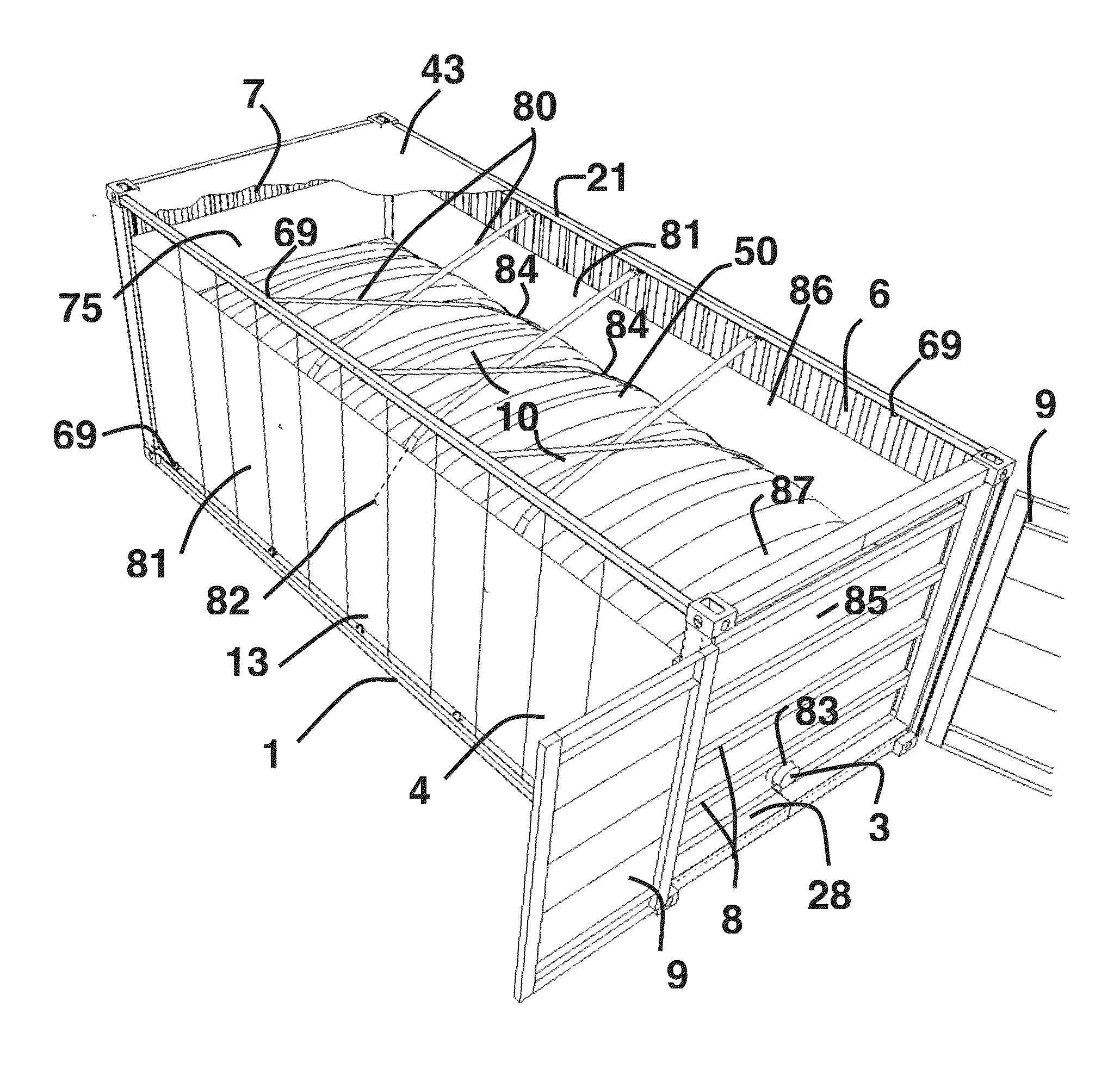
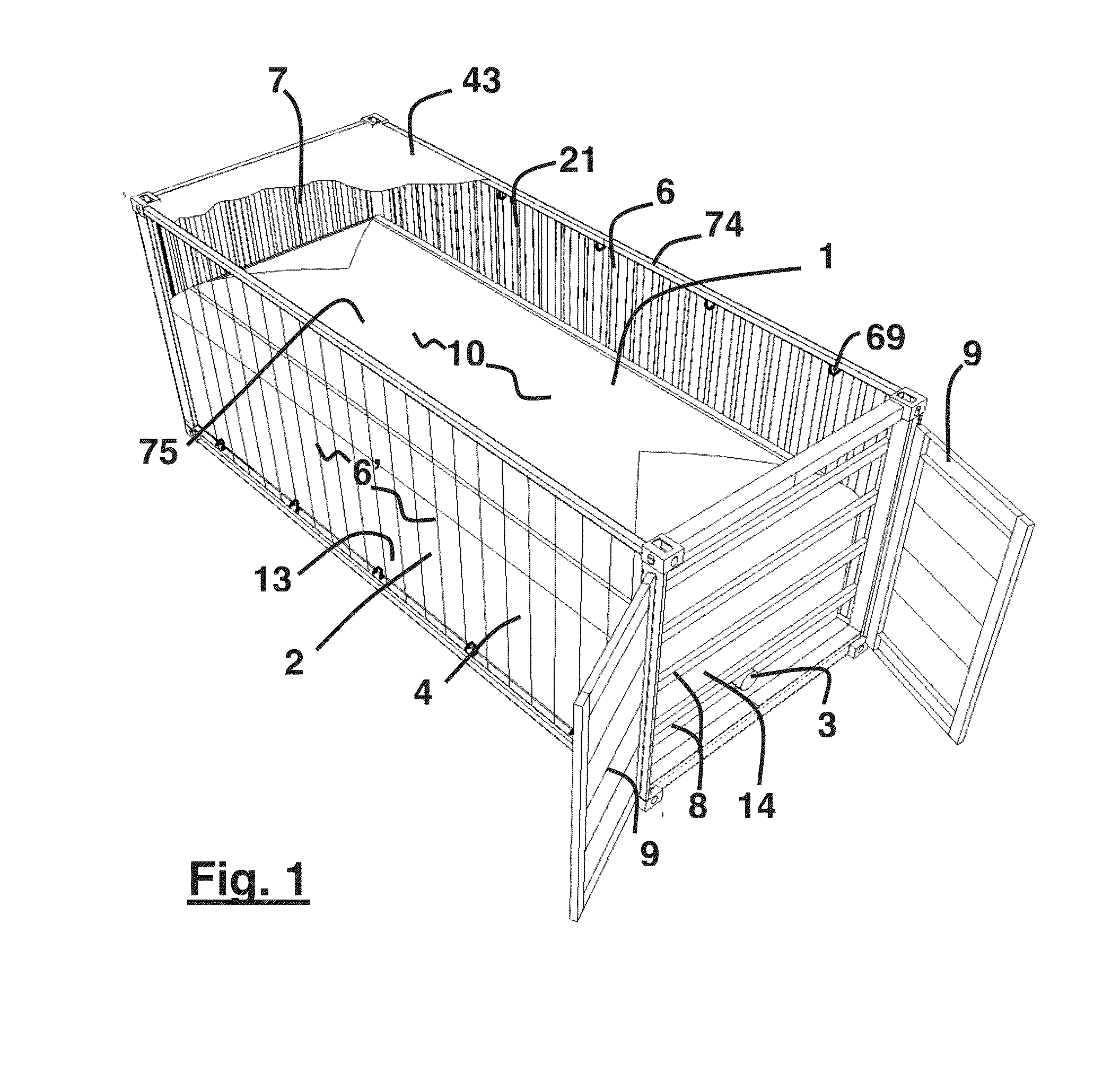
[0036]FIG. 1 shows three-quarter 3D perspective ghosted view of an otherwise standard format container with internal flexible wall tank disposed as an internal liner for liquid storage;

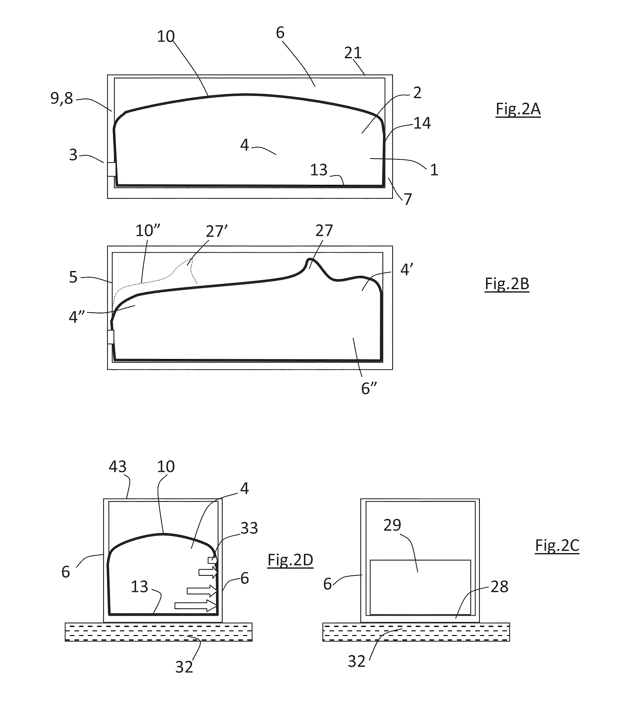
[0037]FIGS. 2A through 2D show variously longitudinal and cross-sections of the tank of FIG. 1 and the behaviour of liquid content in the flexible wall tank bag under shunt and cornering loads;

[0038]More specifically . . . .

[0039]FIG. 2A shows a longitudinal section of a static unloaded (aside from its own passive weight and that of its liquid contents) bag of shallow domed form, sat snug within container longitudinal confines but with a gap overhead between respective bag and container roofs;

[0040]FIG. 2B shows the bag of FIG. 2A under sh...


PUM


Abstract

A flexible walled bag, tank (1), or flexitank, for shipping fluids, in particular liquids, disposed within an outer container (12) confines, and supportable by a container floor, side walls and end structures, an upper tank surface being constrained, loaded or biassed, by external restraints, such as depending local spaced intrusions or baffles (22) extending from one side towards the other.

Description

CROSS REFERENCE TO RELATED APPLICATIONS[0001]This application is a continuation of co-pending application Ser. No. 13 / 461,810, filed on May 2, 2012. No other claim of priority is made in this application.FIELD OF THE INVENTION[0002]This invention relates to the containerisation of bulk liquid storage and transport and is particularly, but not exclusively concerned with stabilising liquid contents under dynamic loads and thereby reducing stresses upon a container structure. The relative volumetric capacities of bag and container and / or the degree of bag inflation or fill and proportion of residual unoccupied interstitial or intervening space between bag outer and container inner impacts upon bag behaviour under liquid fill and in motion under accelerative and braking ‘g’ forces and even simply brisk lifting or lowering.TERMINOLOGY[0003]Where the context allows, for convenience on occasion alternative terms are used for corresponding parts, such as references to a bag surface or alter...

Claims


Application Information

Patent Timeline
Patent Type & Authority Applications(United States)
IPC IPC(8): B65D25/16B65D88/02
CPCB65D88/02B65D25/16B65D90/048B65D90/52B65D2590/046
Inventor CLIVE-SMITH, MARTINCLIVE-SMITH, MILLIE
Owner CLIVE SMITH MARTIN
Why Eureka
Try Eureka