Eureka AIR delivers breakthrough ideas for toughest innovation challenges, trusted by R&D personnel around the world.

Squirting toy including a dynamo system and methods thereof

a dynamo system and squirting toy technology, applied in the field of squirting toy, can solve the problems of limiting the use of liao's squirting toy, failing to work without battery replacement, so as to achieve the effect of increasing reducing the volume of the chamber

Active Publication Date: 2014-09-11
EASEBON SERVICES
View PDF3 Cites 4 Cited by
  • Summary
  • Abstract
  • Description
  • Claims
  • Application Information

AI Technical Summary

Benefits of technology

The patent describes a water squirting toy that has a housing with a nozzle end and a variable volume chamber. The chamber volume can be adjusted by the user to control the flow of water through the nozzle. The improvement features an electrical generating assembly that can power an electric device using the water that is being squirtered. This allows for the toy to generate electricity as it sucks water through the nozzle.

Problems solved by technology

Additionally, many squirt guns of the prior art are constructed in a manner that entraps air and thereby inadvertently enables those guns to partially float in water, but do not float when no air is entrapped.
However, as the batteries lose power illumination or sound making tends to decrease and eventually fails to work without replacement of the batteries.
These systems also require wiring and other electronics offset from the batteries which can fail when exposed to moisture.
Liao's squirting toy is thereby restricted for use by the range of the hose (tether) since electricity can only be generated when the squirting toy receives water from the hose.

Method used


Image

  • Squirting toy including a dynamo system and methods thereof
  • Squirting toy including a dynamo system and methods thereof
  • Squirting toy including a dynamo system and methods thereof

Examples


Embodiment Construction

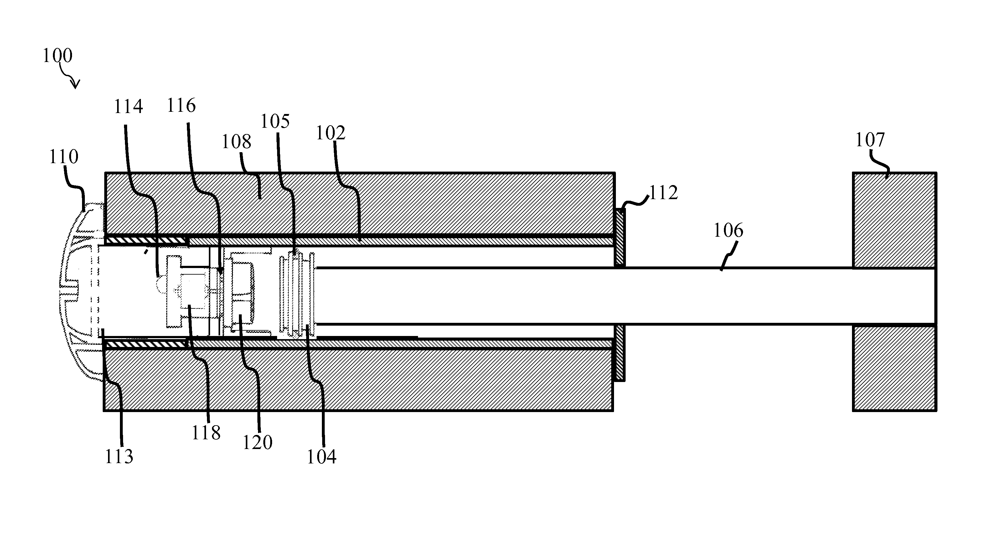
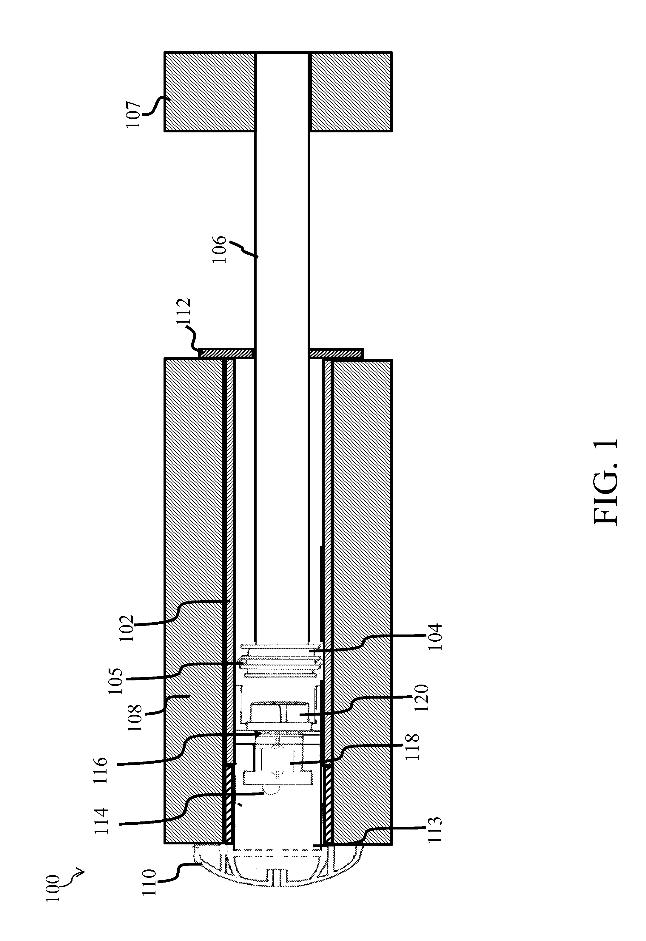
[0042]Referring to FIG. 1, in exemplary embodiments, a squirting toy 100 can include a housing 102 surrounding a piston 104, piston 104 can be attached to a shaft 106, and at least some portion of housing 102 can be surrounded by a shell 108. In exemplary embodiments, a nozzle 110 can be located at one end of the housing for accelerating water pushed by piston 104 inside housing 102 out of housing 102. In exemplary embodiments, a slide bushing 112 can be located at one end of the housing 102 that can retain piston 104 within housing 102. In exemplary embodiments, force can be applied to handle portion 107 causing piston 104 to displaceably move along the length of housing 102. Piston 104 can include one or more seals 105 (e.g., “o” rings, etc.).

[0043]In exemplary embodiments, squirting toy 100 can include a turbulent control member 113. Turbulent control member 113 can be used to decrease turbulent water flow and / or increase laminar water flow from the exit of nozzle 110. Turbulent ...


PUM


Abstract

A squirting toy capable of squirting water received from a reservoir and / or from an external source. The squirting toy can include a housing, a piston, a shaft, and an handle portion. As the piston is slidably moved through the housing the water can be squirted out of the housing. Further, as the piston is slidably moved through the housing an electrical assembly including a turbine can be activated generating electricity to power an electric device (e.g., a light).

Description

FIELD OF THE INVENTION[0001]The present invention relates to a squirting toy capable of converting the squirting toy's user driven fluid flow from mechanical energy to electrical energy prior to exhausting the fluid from the squirting toy.BACKGROUND[0002]Squirt guns are well known in many forms in the prior art. Numerous squirt guns and squirting toys are made and have been made over the years for use by persons while swimming in or standing adjacent to a swimming pool, which are adapted to quickly take in water from the swimming pool for squirting. One such toy is called MAX LIQUIDATOR™ and is sold by Prime Time Toys Ltd. This toy, representative of many such squirting toys, is basically comprised of a housing having a nozzle at its squirting end. A piston, which includes a graspable handle, is adapted to slide within the housing so that, when the nozzle end of the housing is submerged in the pool and the piston is pulled backwards, water is drawn into the housing through the nozzl...

Claims


Application Information

Patent Timeline
Patent Type & Authority Applications(United States)
IPC IPC(8): F41B9/00
CPCF41B9/0078F41B9/0037F41G1/35
Inventor CHIA, FRANCIS SEE CHONG
Owner EASEBON SERVICES
Why Eureka
Eureka Blog
Learn More