Method for molding annular member and apparatus for molding annular member

a technology of annular member and annular member, which is applied in the direction of dough shaping, manufacturing tools, food shaping, etc., can solve the problems of difficult adjustment of bonding position and the length of the bead, and achieve the effect of eliminating the difference in level at the bonded portion

Inactive Publication Date: 2014-09-11
TOYO TIRE & RUBBER CO LTD
View PDF3 Cites 3 Cited by
  • Summary
  • Abstract
  • Description
  • Claims
  • Application Information

AI Technical Summary

Benefits of technology

[0008]A working-effect of the method for molding an annular member according to the above-described configuration will be described. According to this configuration, the thick-walled inner peripheral part can be extruded and molded by the first extruder, and the thin-walled outer peripheral part can be extruded and molded by the second extruder. The first extruder extrudes rubber onto the molding table through the first die provided with the opening having the same cross-sectional shape as the inner peripheral part, and the second extruder extrudes rubber onto the molding table through the second die provided with the opening having the same cross-sectional shape as the outer peripheral part. Therefore, even if thicknesses of the inner peripheral part and the outer peripheral part are largely different from each other, it is possible to accurately mold the inner peripheral part and the outer peripheral part. Further, although the outer peripheral part is thin, since the outer peripheral part is extruded and molded through the second die provided with the opening having the same cross-sectional shape as the outer peripheral part, it is possible to accurately mold the outer peripheral part into a predetermined cross-sectional shape. As a result, according to the method for molding an annular member of the present invention, even if the annular member has a thick-walled inner peripheral part and a thin-walled outer peripheral part, it is possible to accurately mold the annular member into a predetermined cross-sectional shape. In the present invention, any one of a step of molding an inner peripheral part and a step of molding an outer peripheral part may be carried out first, or both the steps may be carried out at the same time. Alternatively, one of the steps may be started halfway through the other step.
[0010]According to this configuration, the bead core which serves as a benchmark when the inner peripheral part is molded is previously placed on the molding table. Therefore, it is easy to mold the inner peripheral part, and also when the outer peripheral part is molded, since the inner peripheral part which is already molded exists on the molding table, it is easy to mold the outer peripheral part.
[0012]Rubber is extruded into an annular shape by the first extruder onto the molding table while the molding table is rotated, thereby molding the inner peripheral part. The inner peripheral part is thick and thus, if the inner peripheral part is not accurately cut into a predetermined length, a difference in level is prone to appear at a bonded portion between the ends. According to the above-described configuration, in the step of molding the inner peripheral part, the first extruder is made to approach the forming surface of the molding table which is under suspension, the extruded rubber is adhered to the forming surface and rotation of the molding table is started at the same time. According to this, the pasting motion of rubber on the forming surface is started, and after the pasting motion of rubber on the forming surface is started, the extruding speed of rubber is gradually accelerated up to the given speed, and the first extruder is gradually separated from the forming surface up to a given distance. According to this, a thickness of rubber which is pasted on the molding table gradually becomes thick. On the other hand, immediately before the pasting motion of rubber on the forming surface is completed, the extruding speed of rubber is gradually decelerated from the given speed. According to this, a thickness of rubber pasted on the molding table gradually becomes thin. According to this, when the end of rubber at a pasting starting position and the end of rubber at a pasting ending position are bonded to each other, a rubber thickness-gradually increasing portion and a rubber thickness-gradually reducing portion are superposed on each other, thereby eliminating a difference in level at the bonded portion. After the pasting motion of rubber is started, the extruding speed of rubber is gradually accelerated, and the first extruder is gradually separated from the forming surface up to the given distance. According to this, even if the thickness of rubber gradually becomes thick, it is possible to prevent the first extruder and rubber pasted on the forming surface from coming into contact with each other.
[0014]The working-effect of the apparatus for molding an annular member according this configuration is as described above. Even if the annular member includes a thick-walled inner peripheral part and a thin-walled outer peripheral part, it is possible to accurately mold the annular member into a predetermined cross-sectional shape.

Problems solved by technology

However, according to the method of pasting the cut ends to each other to form them into the annular shape, an entire length of the bead filler is varied due to shrinkage or the like of the bead filler and it becomes difficult to adjust the bonding position in some cases.

Method used


Image

  • Method for molding annular member and apparatus for molding annular member
  • Method for molding annular member and apparatus for molding annular member
  • Method for molding annular member and apparatus for molding annular member

Examples


Embodiment Construction

[0024]

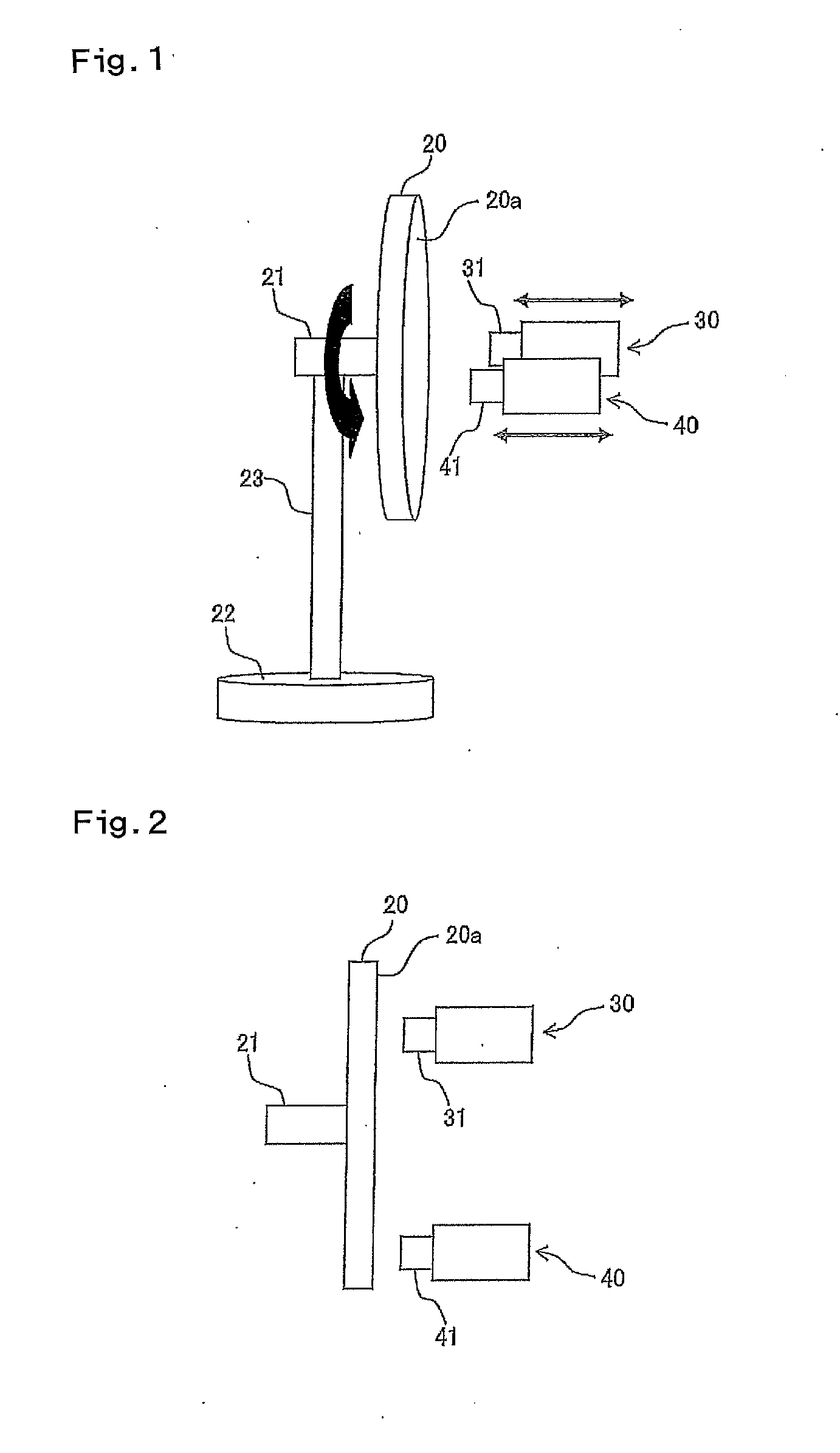
[0025]Embodiments of the present invention will be described below with reference to the drawings. FIG. 1 is a perspective view of an outward appearance showing a schematic configuration of a apparatus for molding an annular member according to the present invention. FIG. 2 is a plan view, from the above, of the apparatus for molding an annular member shown in FIG. 1. FIG. 3 is a partially cut-away perspective view of a bead member. FIG. 4 is a sectional view of a bead filler.

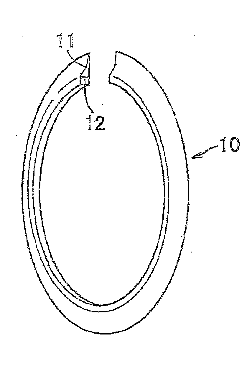
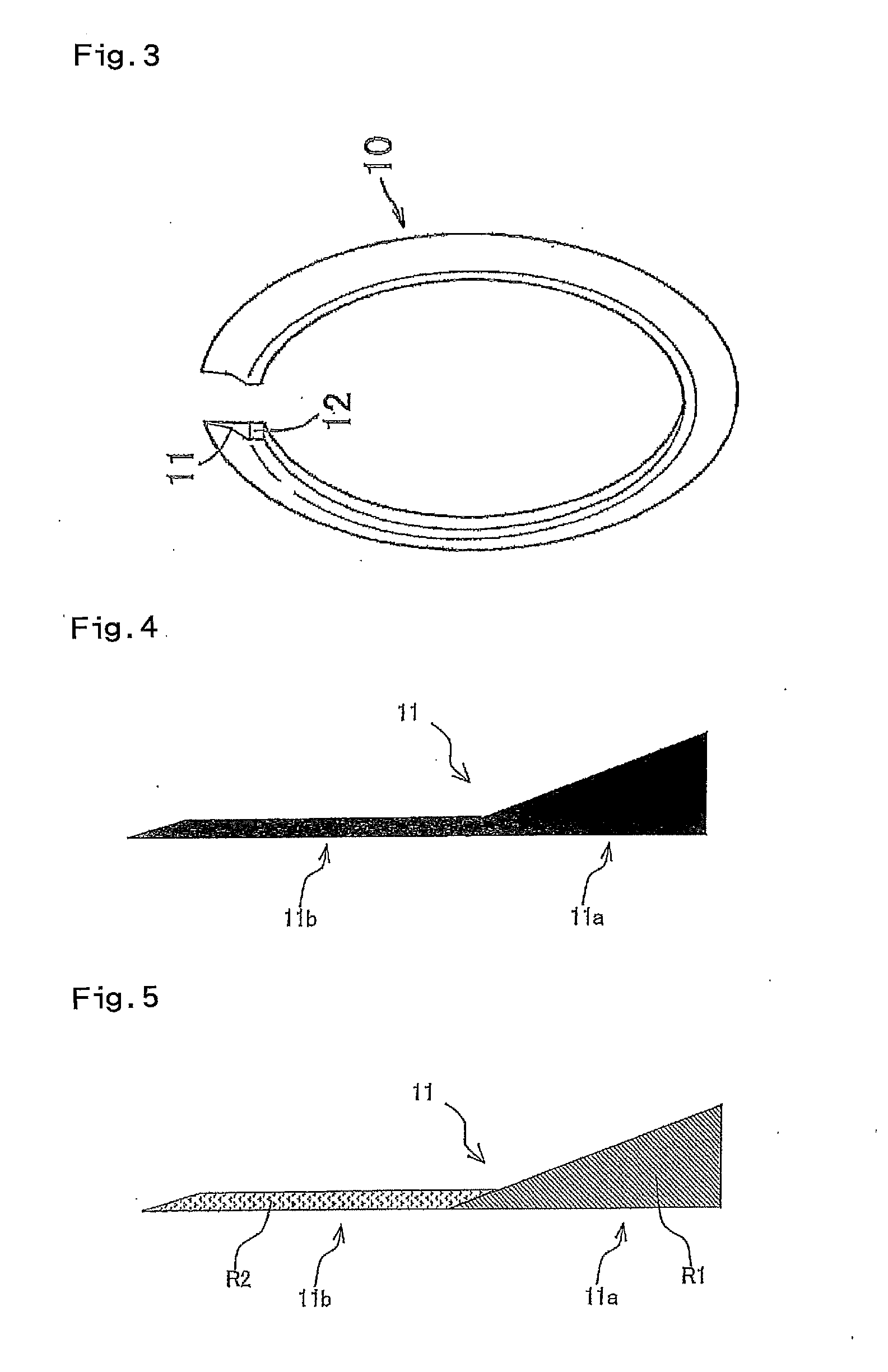
[0026]In this embodiment, the annular member is a bead filler 11. As shown in FIG. 3, the bead filler 11 is placed on an outer periphery of a bead core 12, and the bead filler 11 and the bead core 12 configure a bead member 10.

[0027]A cross-sectional shape of an inner peripheral part 11a of the bead filler 11 is substantially triangular, and a cross-sectional shape of an outer peripheral part 11b of the bead filler 11 is rectangular having a substantially constant thickness. An outer peripheral end is tap...


PUM

PropertyMeasurementUnit
shapeaaaaaaaaaa
cross-sectional shapeaaaaaaaaaa
speedaaaaaaaaaa

Abstract

The object of the present invention is to provide a method and an apparatus for molding an annular member capable of accurately molding an annular member into a predetermined cross-sectional shape even if the annular member has a thick-walled inner peripheral part and a thin-walled outer peripheral part. The method for molding a bead filler (11) including a thick-walled inner peripheral part (11a) and a thin-walled outer peripheral part (11b), the method comprising the steps of extruding, into an annular shape, rubber (R1) by a first extruder (30) onto a molding table (20) through a first die (31) provided with an opening having the same cross-sectional shape as that of the inner peripheral part (11a) while the molding table (20) is rotated, and molding the inner peripheral part (11a); and extruding, into an annular shape, rubber by a second extruder (40) onto the molding table (20) through a second die (41) provided with an opening having the same cross-sectional shape as that of the outer peripheral part (11b) while the molding table (20) is rotated, and molding the outer peripheral part (11b).

Description

TECHNICAL FIELD[0001]The present invention relates to a method and an apparatus for molding an annular member including a thick-walled inner peripheral part and a thin-walled outer peripheral part.BACKGROUND ART[0002]A bead member which is one of tire constituent members includes an annular bead filler having a triangular cross section and made of hard rubber, and a bead core formed from a rubber-coated convergent body such as a steel wire. The bead member is produced in such a manner that a bead filler is extruded by an extruder into a band shape through a die, the bead filler is supplied to a bead core which is previously formed into an annular shape, and the bead filler is pasted on an outer peripheral part of the bead core (see Patent Document 1). After the bead filler is cut into a predetermined length, ends thereof are pasted on each other and formed into an annular shape.[0003]However, according to the method of pasting the cut ends to each other to form them into the annular...

Claims


Application Information

Patent Timeline
Patent Type & Authority Applications(United States)
IPC IPC(8): B29D99/00B29C48/07B29C48/12B29C48/155
CPCB29D99/0082B29D30/48B29D2030/482B29D2030/487B29C48/07B29C48/12B29C48/131B29C48/155B29C48/266
Inventor TSUBOTANI, SOUSUKEMIYAMOTO, RYOSHI
Owner TOYO TIRE & RUBBER CO LTD
Why Eureka
Try Eureka