
Measuring Instrument

a technology of measuring instruments and measuring rods, applied in instruments, distance measurement, surveying and navigation, etc., can solve the problems of deterioration in accuracy and high price of measuring rods

Active Publication Date: 2014-09-11
KK TOPCON
View PDF2 Cites 15 Cited by
  • Summary
  • Abstract
  • Description
  • Claims
  • Application Information

AI Technical Summary

Benefits of technology

The present invention provides an affordable measuring instrument that can easily self-localize and prepare a three-dimensional point cloud model. It includes a spherical camera and a laser scanner for acquiring image and point cloud data. An absolute scale acquiring unit extracts an absolute scale from an image and calculates an absolute position of the camera. A control arithmetic unit calculates a 3D model based on the image and point cloud data, as well as combines the 3D models to create a wide-area 3D model of the entire measurement range. This invention allows for efficient and accurate measurements in various settings without the need for GPS.

Problems solved by technology

However, IMU is expensive, and there are problems such as deterioration in accuracy is caused by a drift or a calibration is troublesome.

Method used


Image

  • Measuring Instrument
  • Measuring Instrument
  • Measuring Instrument

Examples


Embodiment Construction

[0025]Description will be given below on an embodiment of the present invention by referring to the attached drawings.

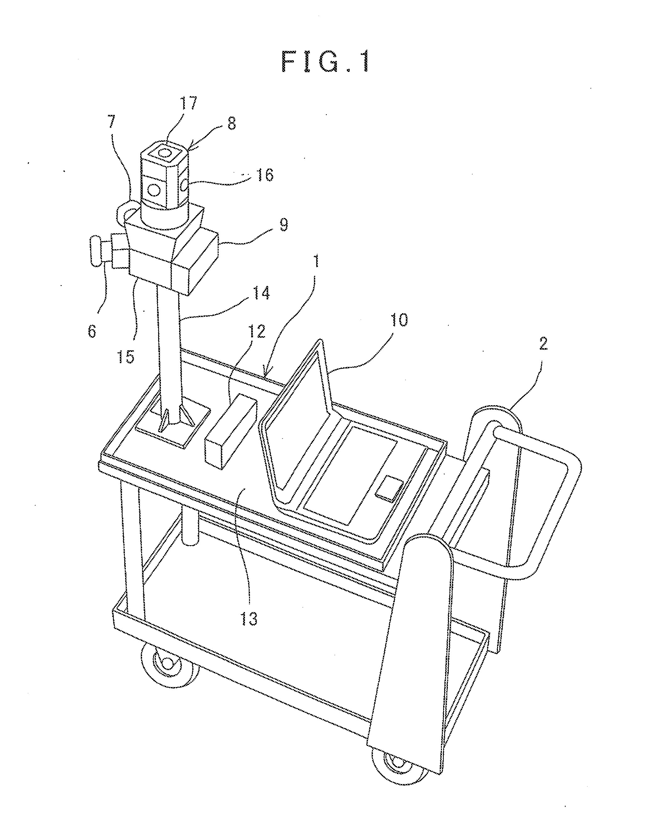
[0026]In FIG. 1, reference numeral 1 denotes a measuring instrument, and reference numeral 2 denotes a moving vehicle 2, on which the measuring instrument 1 is installed. Although a carrying cart is shown in the figure as the moving vehicle 2, it would suffice that the measuring instrument 1 can be installed on the moving vehicle 2 and can be moved. Further, the moving vehicle 2 may be designed as a self-running type or a remotely operable type, and there is no special restriction on the moving vehicle 2.

[0027]Description will be given on the measuring instrument 1.

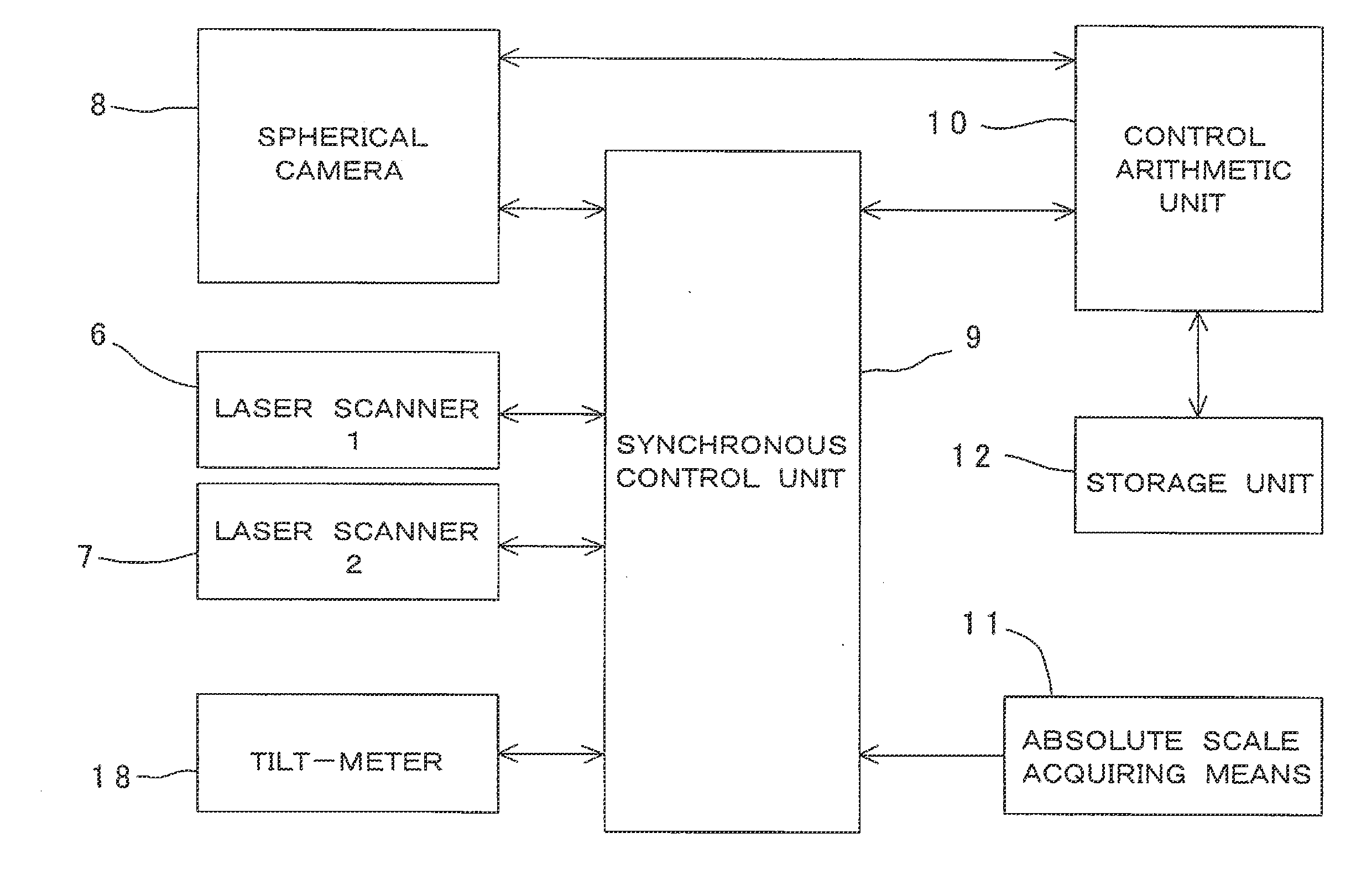
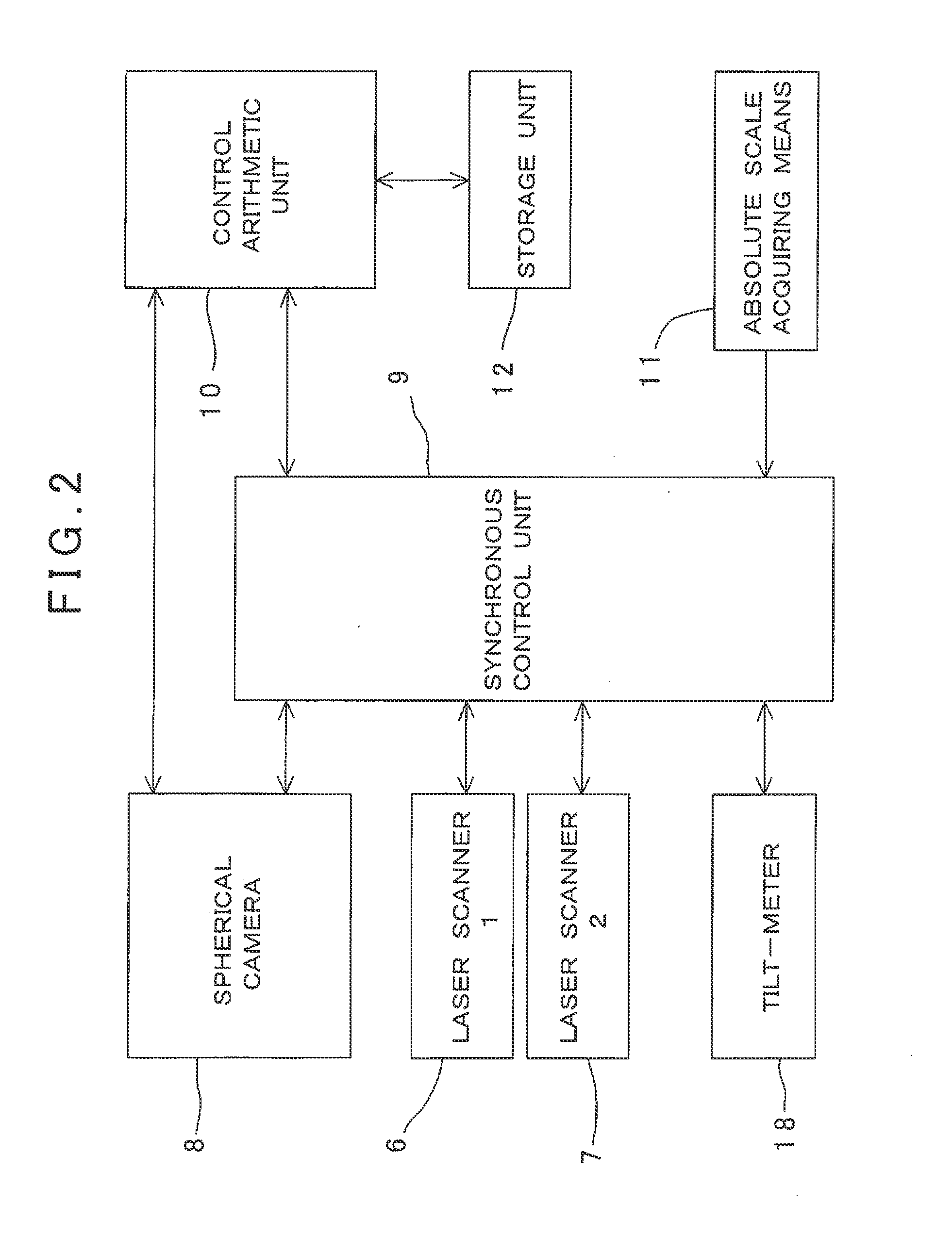
[0028]The measuring instrument 1 primarily comprises laser scanners 6 and 7, an spherical camera 8, a synchronous control device 9, a control arithmetic unit (PC) 10, an absolute scale acquiring means 11, and a storage unit 12. The laser scanners 6 and 7 and the spherical camera 8 are in an integrated cond...


PUM


Abstract

A measuring instrument comprises an spherical camera (8) for acquiring image data over total circumference, a laser scanner (6, 7) installed integrally with the spherical camera and for acquiring point cloud data of the surroundings, a synchronous control unit (9) for controlling acquisition of data of the spherical camera and the laser scanner, a storage unit (12) for recording the image data and the point cloud data, an absolute scale acquiring means for acquiring an absolute scale for obtaining an absolute position of when images are photographed by the spherical camera, and a control arithmetic unit (10), wherein the control arithmetic unit calculates a 3D model based on the image data, the point cloud data, and the absolute position.

Description

BACKGROUND OF THE INVENTION[0001]The present invention relates to a measuring instrument, by which three-dimensional measurement can be accomplished under a circumstance where position measurement by the GPS cannot be carried out such as an indoor space or a tunnel, etc.[0002]In a case of the measurement of indoor space, tunnel, etc., an attention has been drawn on a system in which scanning is performed by moving a one-dimensional (line) laser scanner, and a three-dimensional point cloud model of the entirety is prepared while moving.[0003]In order to prepare the three-dimensional point cloud model, it is necessary to specify a position (self-localization) from which measurement is carried out. Further, the GPS has become widespread as a measuring system for specifying the self-localization, but normally, in a case where the place of measurement is indoor space, tunnel, etc., the GPS for specifying self-localization is in an environment where the GPS cannot be used.[0004]As means f...

Claims


Application Information

Patent Timeline
Patent Type & Authority Applications(United States)
IPC IPC(8): H04N13/02
CPCH04N13/0275G01C3/00G01C11/06H04N13/275
Inventor KUMAGAI, KAORUOTANI, HITOSHIKASORI, NAOTOSASAKI, YOUSASAGAWA, JUNFUKAYA, NOBUYUKI
Owner KK TOPCON
Learn More