Electric power conversion system

Active Publication Date: 2014-09-11
TOYOTA JIDOSHA KK
View PDF5 Cites 10 Cited by
  • Summary
  • Abstract
  • Description
  • Claims
  • Application Information

AI Technical Summary

Benefits of technology

[0010]An aspect of the invention provides an electric power conversion system. The electric power conversion system includes: a primary electric power conversion circuit including: a left arm including a left arm upper transistor and a left arm lower transistor connected in series with each other at a left arm connection point between a positive electrode bus and a negative electrode bus; a right arm including a right arm upper transistor and a right arm lower transistor connected in series with each other at a right arm connection point between the positive electrode bus and the negative electrode bus; and a primary coil connected and arranged between the left arm connection point and the right arm connection point; a secondary electric power conversion circuit configured similarly to the primary electric power conversion circuit and including a secondary coil corresponding to the primary coil; and a control circuit configured to control transfer of electric power between the primary electric power conversion circuit and the secondary electric power conversion circuit by magnetically coupling the primary coil to the secondary coil, wherein the control circuit is configured to set the interphase difference γ1 in switching between the left arm lower transistor and the right arm lower transistor in the primary electric power conversion circuit and the interphase difference γ2 in switching between the left arm lower transistor and the right arm lower transistor in the secondary electric power conversion circuit on the basis of an off time δ1 of the primary electric power conversion circuit and an off time δ2 of the secondary electric power convers

Problems solved by technology

However, if the primary electric power conversion circuit and the secondary electric power conversion circuit are caused to operate in a state where an off time δ1 of the primary electric power conversion circuit and an off time δ2 of the secondary electric power conversion circuit are different from each other, the relationship between the

Method used


Image

  • Electric power conversion system
  • Electric power conversion system
  • Electric power conversion system

Examples


Embodiment Construction

[0018]Hereinafter, an embodiment of the invention will be described in detail with reference to the accompanying drawings. Like reference numerals denote similar elements in all the drawings, and the overlap description is omitted below.

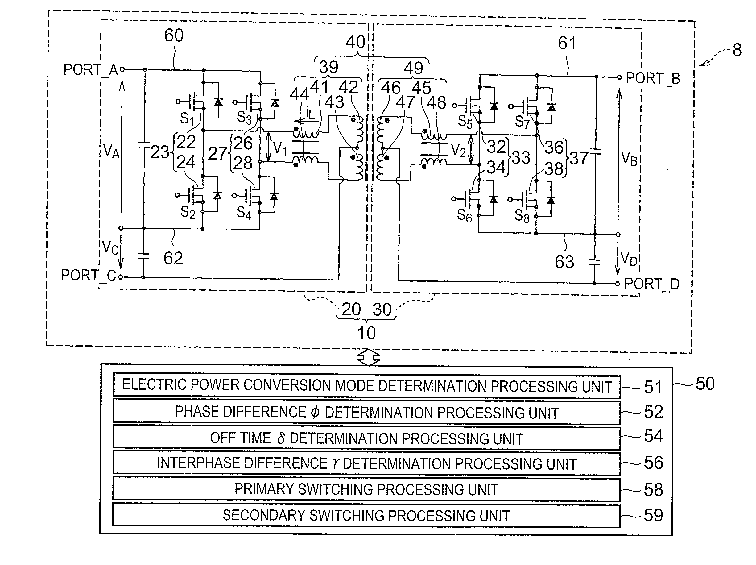
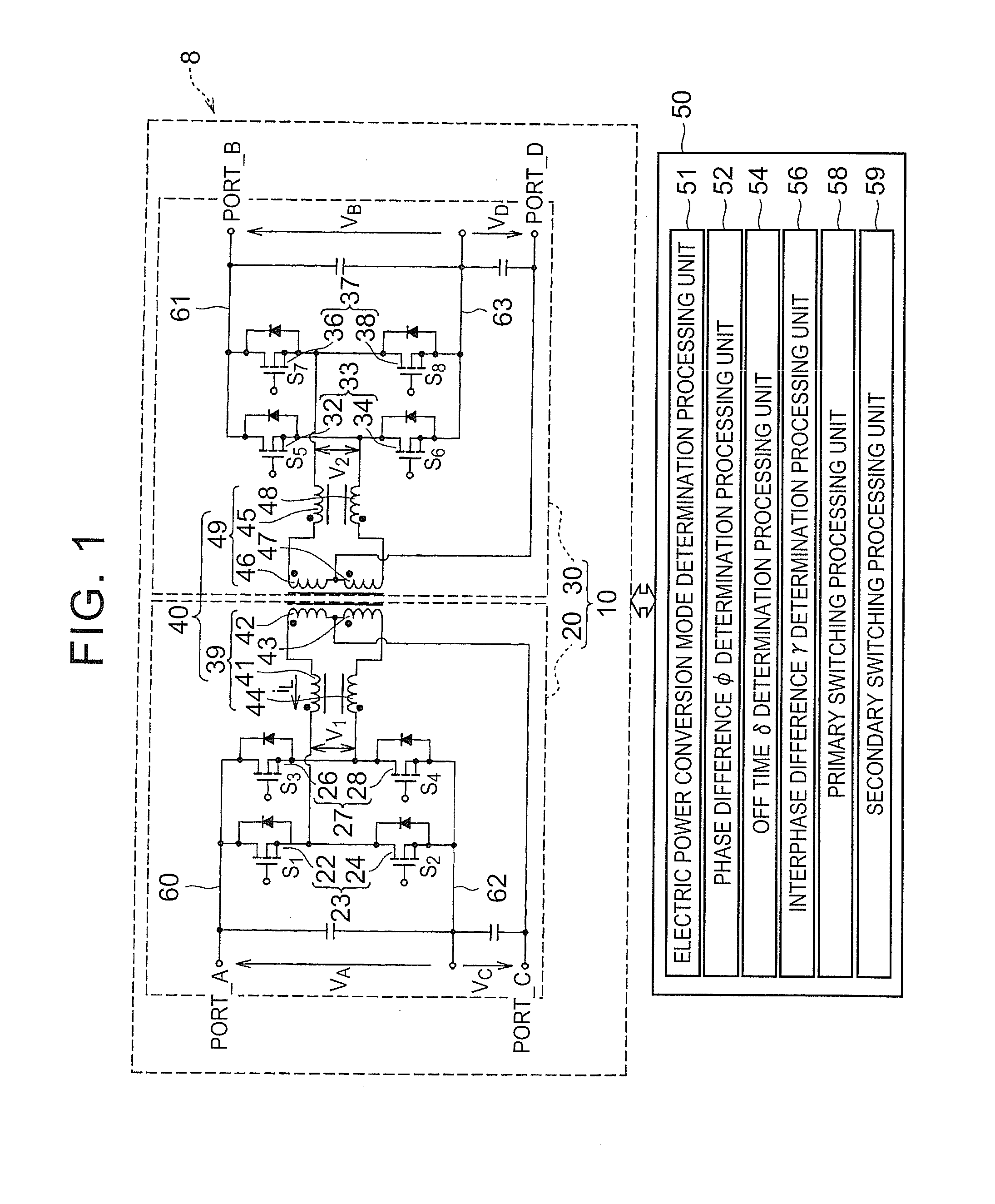
[0019]FIG. 1 is a view that shows an electric power conversion system 8. The electric power conversion system 8 is configured to include an electric power conversion device 10 and a control circuit 50. The electric power conversion device 10 has the function of selecting any two input / output ports from among four input / output ports and converting electric power between the selected two input / output ports. The electric power conversion device 10 is configured to include a primary electric power conversion circuit 20 and a secondary electric power conversion circuit 30. The primary electric power conversion circuit 20 and the secondary electric power conversion circuit 30 are magnetically coupled to each other by a transformation circuit 40.

[0020]A pri...


PUM


Abstract

An electric power conversion system includes: a primary electric power conversion circuit including primary right and left arms; a secondary electric power conversion circuit including secondary right and left arms; and a control circuit controlling transfer of electric power between the primary and secondary electric power conversion circuits by magnetically coupling a primary coil to a secondary coil. The control circuit sets an interphase difference in switching between right and left arm lower transistors in the primary electric power conversion circuit and an interphase difference in switching between right and left arm lower transistors in the secondary electric power conversion circuit on the basis of off times of the primary and secondary electric power conversion circuits such that a phase difference between terminal voltage waveforms of the primary and secondary coils is 0 and duty ratios of the terminal voltage waveforms are equal to each other.

Description

INCORPORATION BY REFERENCE[0001]The disclosure of Japanese Patent Application No. 2013-046572 filed on Mar. 8, 2013 including the specification, drawings and abstract is incorporated herein by reference in its entirety.BACKGROUND OF THE INVENTION[0002]1. Field of the Invention[0003]The invention relates to an electric power conversion system and, more particularly, to an electric power conversion system that exchanges electric power between a primary electric power conversion circuit and a secondary electric power conversion circuit.[0004]2. Description of Related Art[0005]There has been developed an electric power conversion system that exchanges electric power between a primary electric power conversion circuit and a secondary electric power conversion circuit magnetically coupled to the primary electric power conversion circuit.[0006]As a related technique of the invention, for example, U.S. Pat. No. 7,408,794 describes an electric power conversion circuit that includes three inp...

Claims


Application Information

Patent Timeline
IPC IPC(8): H02M3/335
CPCH02M3/33546H02M3/33584H02M3/33561
Inventor TAKAGI, KENICHIISHIGAKI, MASANORIUMENO, TAKAJINAGASHITA, KENICHIROHIRANO, TAKAHIROMUTO, JUNTERADA, YASUHARU
Owner TOYOTA JIDOSHA KK
Why Eureka
Try Eureka