Twist septum polarization rotator

a rotor and twist septum technology, applied in the field of polarization rotors, can solve the problems of plurality of layers introducing alignment and/or signal leakage issues, increasing the total number of parts, and complicating manufactur

Active Publication Date: 2014-09-11
COMMSCOPE TECH LLC
View PDF10 Cites 25 Cited by
  • Summary
  • Abstract
  • Description
  • Claims
  • Application Information

AI Technical Summary

Problems solved by technology

However, these additional elements increase the total number of parts, complicating manufacture.
Further, the plurality of layers may introduce alignment and/or signal leakage issues between each of the several plates/layers.
However, insertion and sealing of each pi

Method used


Image

  • Twist septum polarization rotator
  • Twist septum polarization rotator
  • Twist septum polarization rotator

Examples


Embodiment Construction

[0024]The inventors have recognized that, when care is taken to avoid overhanging edges, a polarization rotator with a twist septum may be cost efficiently manufactured with a high level of precision by injection molding, casting or the like, reducing alignment and or sealing issues associated with multiple layer polarization rotation assemblies. Further, in applications in which a high density array of polarization rotators is required, prior issues with access to individual sidewalls, for example for applying through sidewall pin interconnections or the like may be eliminated.

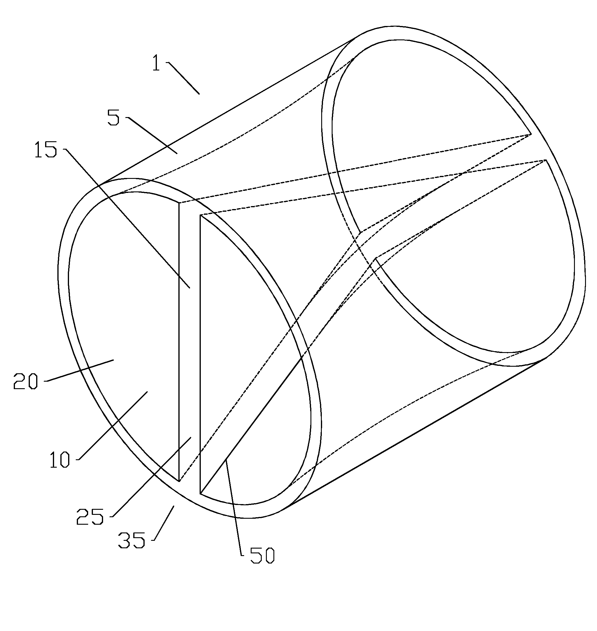
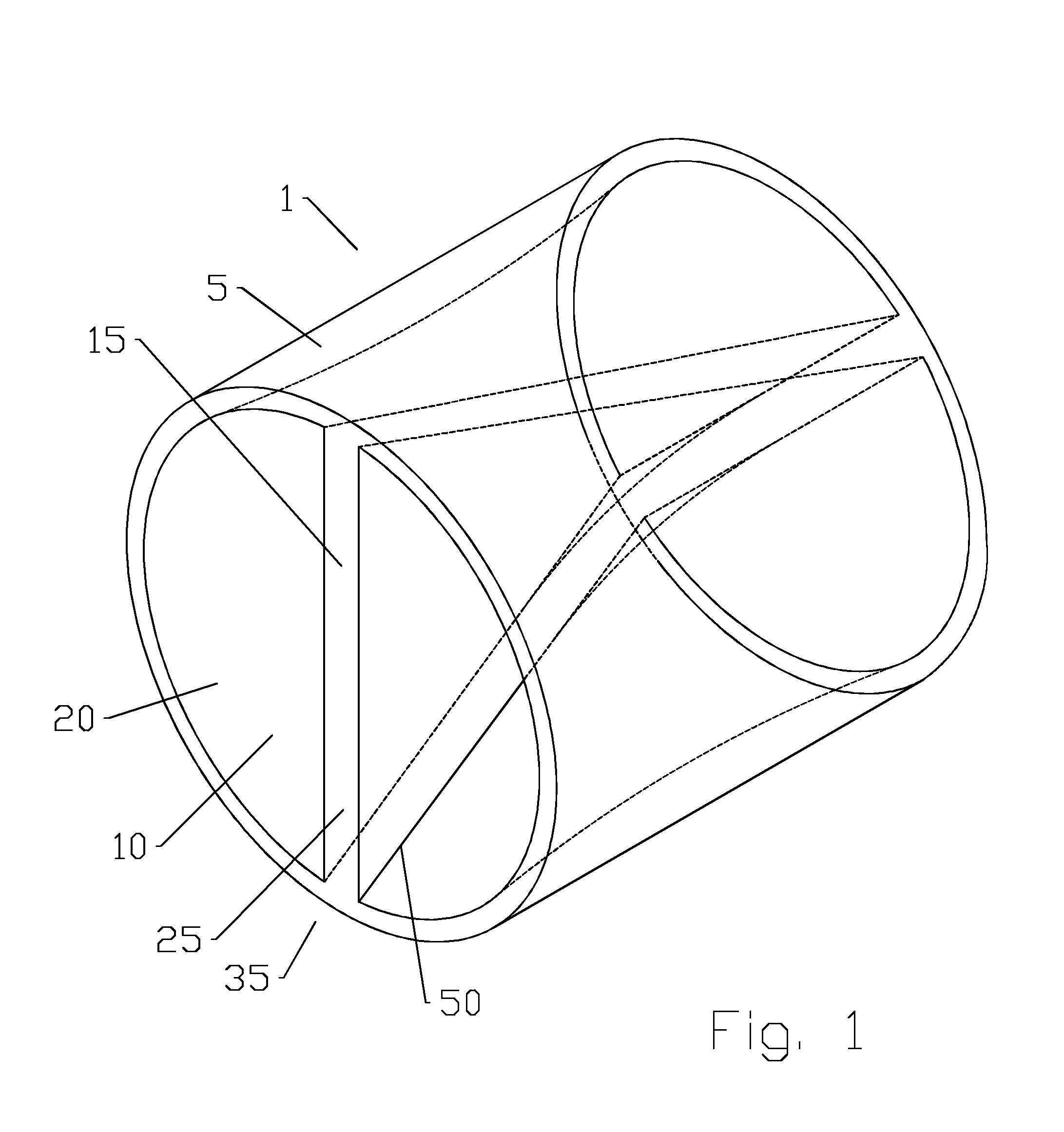
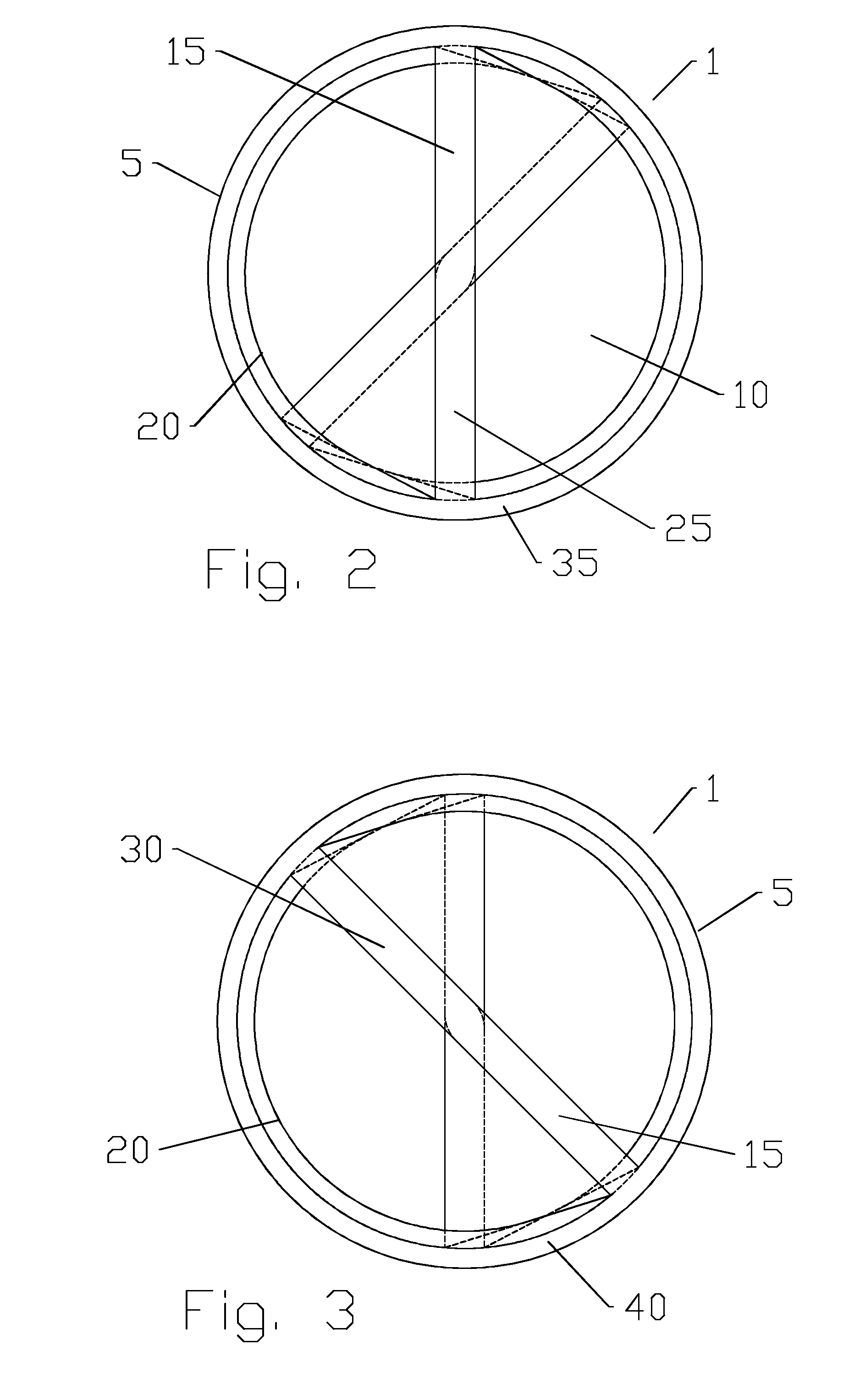
[0025]As shown for example in FIGS. 1-3, an exemplary waveguide polarization rotator 1 has a unitary body 5 with a bore 10 in which a diametral septum 15 of the unitary body 5 extends between the sidewalls 20. The septum 15 twists, along the diameter, between a first end 25 of the septum 15 and a second end 30 of the septum 15. Thereby, an RF signal traveling along the bore 10 has a polarization shift corresp...


PUM

PropertyMeasurementUnit
Fractionaaaaaaaaaa
Angleaaaaaaaaaa
Diameteraaaaaaaaaa

Abstract

A waveguide polarization rotator is provided as unitary body with a first bore; a diametral first septum of the unitary body extending between sidewalls of the first bore. The first septum is twisted between a first end of the first septum and a second end of the first septum. The waveguide polarization rotator may be further provided in a matrix configuration with a plurality of second bores each with a diametral second septum of the unitary body extending between sidewalls of the second bores; a longitudinal axis of the first bore and each of the second bores parallel to one another. The waveguide polarization rotator may be manufactured via injection molding, casting or the like.

Description

BACKGROUND[0001]1. Field of the Invention[0002]This invention relates to equipment useful in high frequency radio communications systems. More particularly, the invention is concerned with a polarization rotator for changing the polarization of signals passing through a waveguide.[0003]2. Description of Related Art[0004]Rotator elements placed in-line with a waveguide are useful for changing the polarization of a signal prior to further processing. Waveguides associated with antennas may include polarization rotation functionality, for example, to allow conversion of the antenna between horizontal and vertical polarization, without requiring rotation of the entire antenna assembly.[0005]The geometries of in-line polarization rotation elements are well known in the art. Transition elements inserted into the electrical signal path progressively rotate the signal through a desired angular rotation, such as ninety degrees between “vertical” and “horizontal” polarization or vice versa. T...

Claims


Application Information

Patent Timeline
IPC IPC(8): G02B6/126
CPCG02B6/126H01P1/173
Inventor THOMSON, ALEXANDER PETERHILLS, CHRISTOPHER D.BIANCOTTO, CLAUDIOEBRAHIMI, ELHAM
Owner COMMSCOPE TECH LLC
Why Eureka
Try Eureka