Tensioning device with spring diaphragm

a technology of a diaphragm and a spring, which is applied in the direction of belts/chains/gears, mechanical equipment, and mechanical devices, and can solve the problems of non-return valve closing and substantial high-dynamic loads on the extending devi

Inactive Publication Date: 2014-09-11
IWIS MOTORSYSTEME GMBH & CO KG
View PDF16 Cites 8 Cited by
  • Summary
  • Abstract
  • Description
  • Claims
  • Application Information

AI Technical Summary

Benefits of technology

[0005]It is therefore the object of the present invention to provide a tensioning device which remains capable of operating even if the supply pressures should be low and which is nevertheless robust as well as cost-efficient.

Problems solved by technology

Due to the fast running endless drive, the tensioning device is subjected to substantial highly dynamic loads that necessitate a fast switching non-return valve which operates efficiently throughout its service life.
However, as soon as the pressure in the pressure chamber exceeds a certain limit, the non-return valve will close.

Method used


Image

  • Tensioning device with spring diaphragm
  • Tensioning device with spring diaphragm
  • Tensioning device with spring diaphragm

Examples


Embodiment Construction

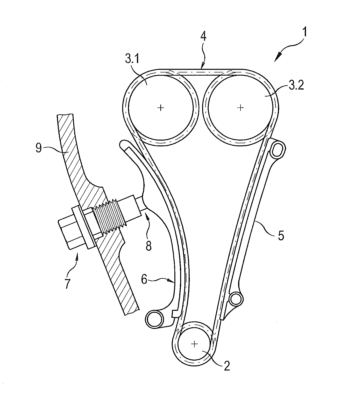
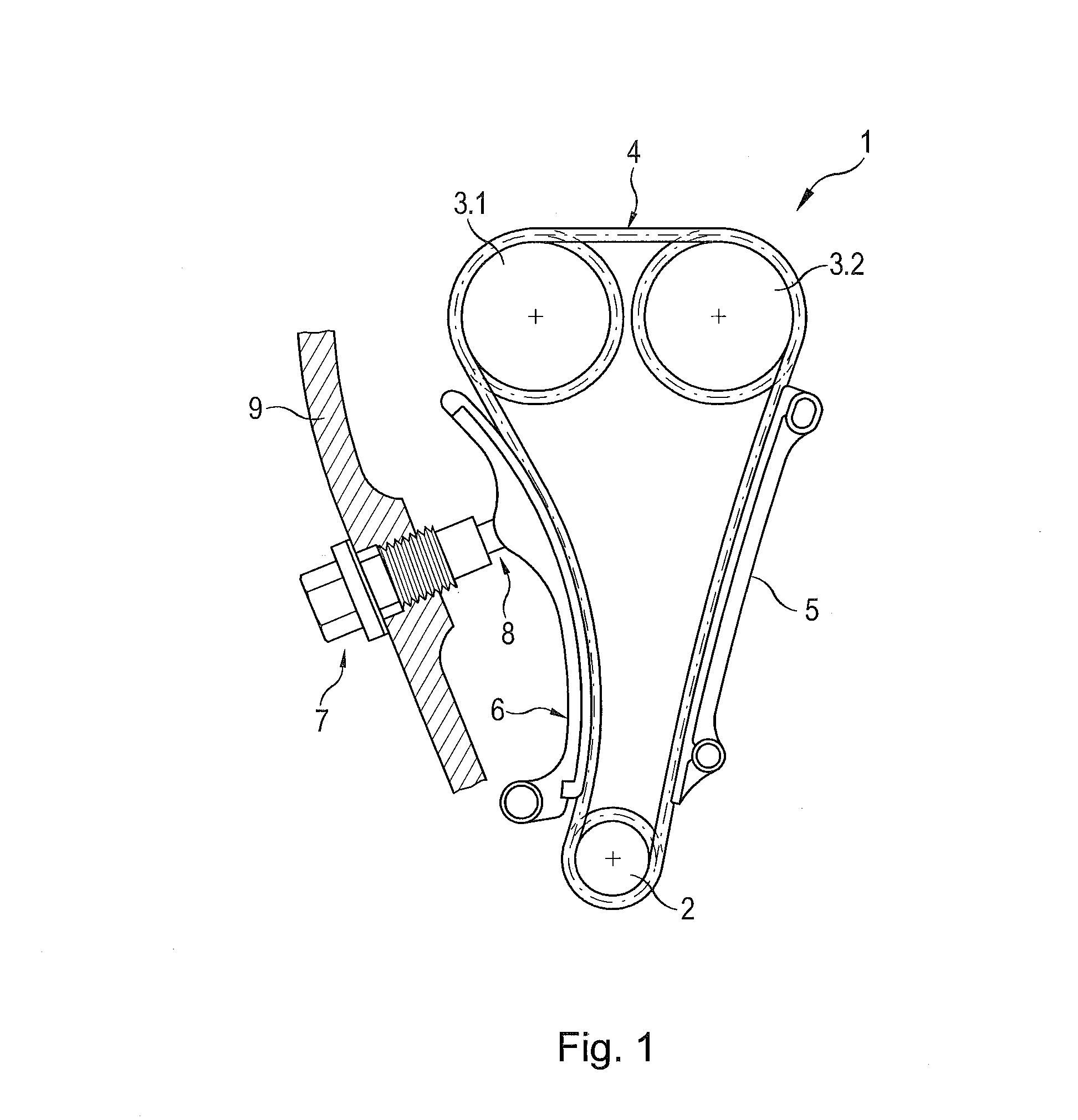
[0032]The timing chain drive 1 for an internal combustion engine shown in FIG. 1 essentially comprises a crankshaft sprocket 2, two juxtaposed camshaft sprockets 3.1 and 3.2, a timing chain 4 wrapped around these sprockets, a chain guide 5 fixed to the engine block, a tensioner blade 6 pivotably arranged on the engine block and a chain tensioner 7 whose tensioning piston 8 presses against the tensioner blade 6. In the present case, the chain tensioner 7 is configured as a so-called screw-in chain tensioner, which is screwed into a wall 9 on the engine case. The chain tensioner 7 may, however, also be configured as a flange- or attachment-type chain tensioner. The crankshaft sprocket 2 drives the two camshaft sprockets 3.1 and 3.2 by means of the timing chain 4. In the course of this process, the tight span of the chain 4 slides along the chain guide 5 and the slack span slides along the tensioner blade 6. The chain tensioner 7 must apply a sufficiently strong force to the tensioner ...


PUM


Abstract

A tensioning device, in particular for a highly dynamic endless drive, such as a chain drive or a belt drive for an internal combustion engine, comprises a tensioner housing, a tensioning piston displaceably arranged in the tensioner housing, a pressure chamber formed between the tensioner housing and the tensioning piston and a pressure medium inlet leading into the pressure chamber and including a non-return valve. In order to meet also new demands, in the case of which oil pumps with having a low feed pressure are used, the present device discloses that a valve body of the non-return valve is defined by a leaf spring diaphragm. The device additionally relates to a non-return valve as well as an endless drive.

Description

CROSS-REFERENCE TO RELATED APPLICATION[0001]This application claims priority to foreign German patent application No. DE 102013004850.8, filed on Mar. 5, 2013, the disclosure of which is incorporated by reference in its entirety.FIELD OF THE INVENTION[0002]The present invention relates to a tensioning device, in particular for a highly dynamic endless drive, such as a chain drive or a belt drive for an internal combustion engine, comprising a tensioner housing, a tensioning piston displaceably arranged in the tensioner housing, a pressure chamber formed between the tensioner housing and the tensioning piston and a pressure medium inlet leading into the pressure chamber and including a non-return valve, a valve body of the non-return valve being defined by a spring diaphragm.BACKGROUND[0003]Such tensioning devices are used e.g. for timing chain drives on an internal combustion engine and they normally press a pivotably arranged tensioner blade with its slide surface against a timing ...

Claims


Application Information

Patent Timeline
Patent Type & Authority Applications(United States)
IPC IPC(8): F16H7/08
CPCF16H7/08F16H7/0836F16H7/0848F16H2007/0806F16H2007/0817F16H2007/0859F16H2007/0893
Inventor LUNK, CHRISTOPHPERISSINOTTO, RENZOSCHOLDERLE, CHRISTIAN
Owner IWIS MOTORSYSTEME GMBH & CO KG
Why Eureka
Try Eureka