Heat pump defrosting system and method

a heat pump and defrosting technology, applied in heat pumps, domestic cooling devices, lighting and heating devices, etc., can solve the problems of reducing the efficiency of the regeneration air heat exchanger, affecting the efficiency of the heat exchanger, so as to reduce the formation of fros

Active Publication Date: 2014-09-18
NORTEK AIR SOLUTIONS CANADA INC
View PDF8 Cites 36 Cited by
  • Summary
  • Abstract
  • Description
  • Claims
  • Application Information

AI Technical Summary

Benefits of technology

[0014]The heat pump system may also include an energy recovery module that extends between the supply air channel and the regeneration air channel. The energy recovery module may be configured to remove heat and moisture from the regeneration air during the normal mode. The heat pump system may also include a control module configured to sense at least one condition of the refrigeration circuit and control the output of the compressor in response to the sensed condition. The control module may also be configured to control operation of the energy recovery module. The control module may be configured to control movement of the hot refrigerant through the refrigeration circuit and the damper(s) in order to reduce frost formation on the energy recovery module or the regeneration air heat exchanger.

Problems solved by technology

However, conventional heat pump systems are not without their disadvantages.
Additionally, during summer modes, the regeneration air heat exchanger may be required to supply large amounts of heat to the regeneration air.
As a result, an efficiency of the regeneration air heat exchanger may substantially decrease.
However, the available energy in a refrigeration system is limited.
Yet, if less energy is provided to the pre-conditioning coil, frost may accumulate more quickly on the regeneration heat exchanger.
As such, energy that is provided to the pre-conditioning coil that is configured to prevent or minimize frost formation on the regeneration air heat exchanger is energy that is not available for the supply air heat exchanger.
However, providing energy to the pre-conditioning coil in such a manner may decrease the overall system efficiency as useful or captured energy in the regeneration heat exchanger is simply expelled to the pre-conditioner and not the supply air heat exchanger.
Heat wires in the drain pan may be used to prevent the re-freezing, yet using additional heating elements may increase the overall power consumption of the system.
Additionally, some heat exchanger fins may be corrugated and have a perforated surface configured to increase turbulence flow on the surface of the fin and ultimately increase heat transfer characteristics.
During the subsequent heating cycle, the remaining water may freeze in the regeneration / return air heat exchanger and reduce the amount of effective run time before the next defrost cycle.

Method used


Image

  • Heat pump defrosting system and method
  • Heat pump defrosting system and method
  • Heat pump defrosting system and method

Examples


Embodiment Construction

[0039]The foregoing summary, as well as the following detailed description of certain embodiments will be better understood when read in conjunction with the appended drawings. As used herein, an element or step recited in the singular and proceeded with the word “a” or “an” should be understood as not excluding plural of said elements or steps, unless such exclusion is explicitly stated. Furthermore, references to “one embodiment” are not intended to be interpreted as excluding the existence of additional embodiments that also incorporate the recited features. Moreover, unless explicitly stated to the contrary, embodiments “comprising” or “having” an element or a plurality of elements having a particular property may include additional such elements not having that property.

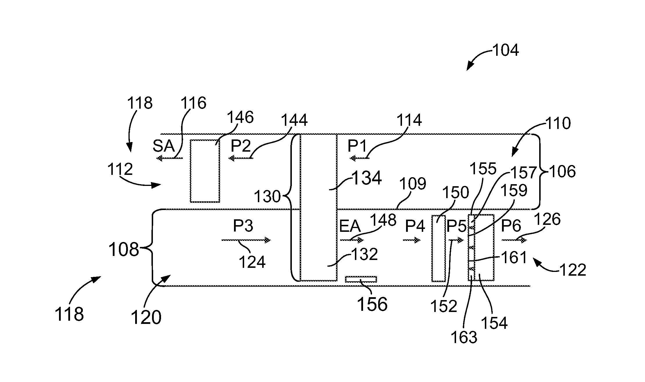
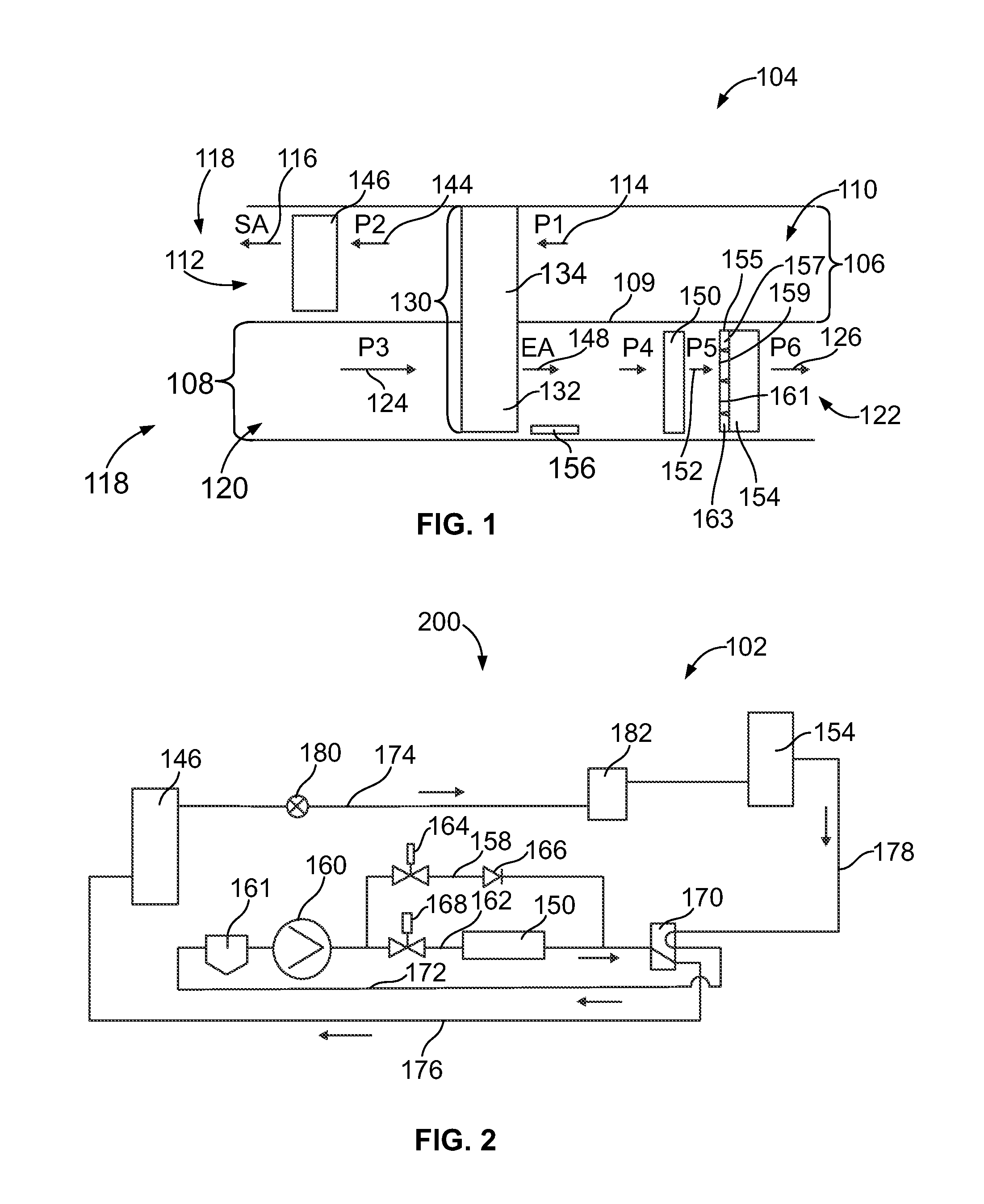
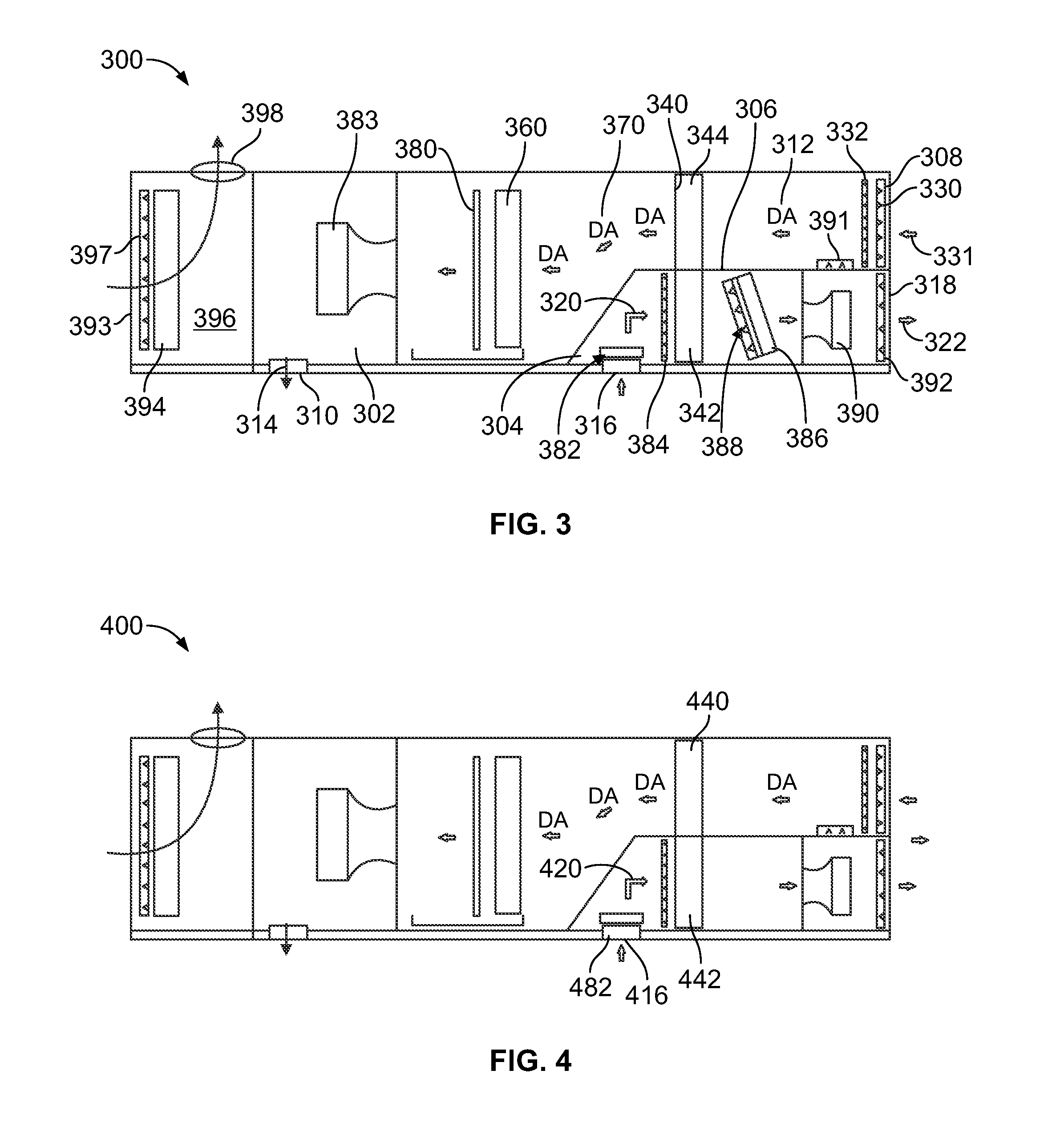
[0040]Embodiments of the present disclosure provide heat pump systems that may include one or more dampers positioned on or proximate to a heat exchanger. The damper(s) are configured to selectively allow and pr...


PUM


Abstract

A heat pump system for conditioning regeneration air from a space is provided. The heat pump system is operable in a winter mode and / or a summer mode, and may be selectively operated in a defrost mode or cycle. During a defrost mode, hot refrigerant may be used to directly and sequentially defrost the regeneration air heat exchanger. A compressor may be configured to be overdriven during a defrost cycle.

Description

CROSS-REFERENCE TO RELATED APPLICATIONS[0001]The present application relates to and claims priority benefits from U.S. Provisional Patent Application No. 61 / 778,681, entitled “Air Source Heat Pump System and Method,” filed Mar. 13, 2013, which is hereby expressly incorporated by reference in its entirety.BACKGROUND OF THE DISCLOSURE[0002]Embodiments of the present disclosure generally relate to a heat pump system and method, and, more particularly, to a system and method of efficiently operating a heat pump in a defrost mode.[0003]An air-to-air heat pump, also known as an air source heat pump (“ASHP”), is generally a heating and cooling system that uses return air, regeneration air and / or outside air as a heat source and heat sink. An ASHP absorbs heat from the return / regeneration air and / or outside air and releases the heat to an enclosed space during a winter mode. Any heat source, including outside air, return air, or regeneration air) that has a temperature above absolute zero c...

Claims


Application Information

Patent Timeline
Patent Type & Authority Applications(United States)
IPC IPC(8): F25B30/02
CPCF25B30/02F25B13/00F25B47/025F25B49/022F25B2400/0403F25B2600/0271F25B2600/0272F25B2700/1931F25B2700/1933F25B2700/21151F25B2700/21152F25B2313/0251F24F11/41F25B6/04Y02B30/52Y02B30/56
Inventor WINTEMUTE, DAVID MARTINBELIVEAU, MATHIEU PHILIPPE
Owner NORTEK AIR SOLUTIONS CANADA INC
Why Eureka
Try Eureka