Methods and systems for liquid desiccant air conditioning system retrofit
- Summary
- Abstract
- Description
- Claims
- Application Information
AI Technical Summary
Benefits of technology
Problems solved by technology
Method used
Image
Examples
Embodiment Construction
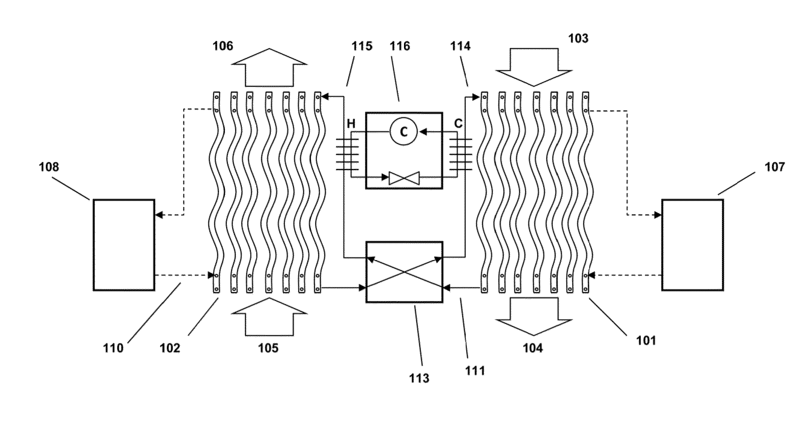
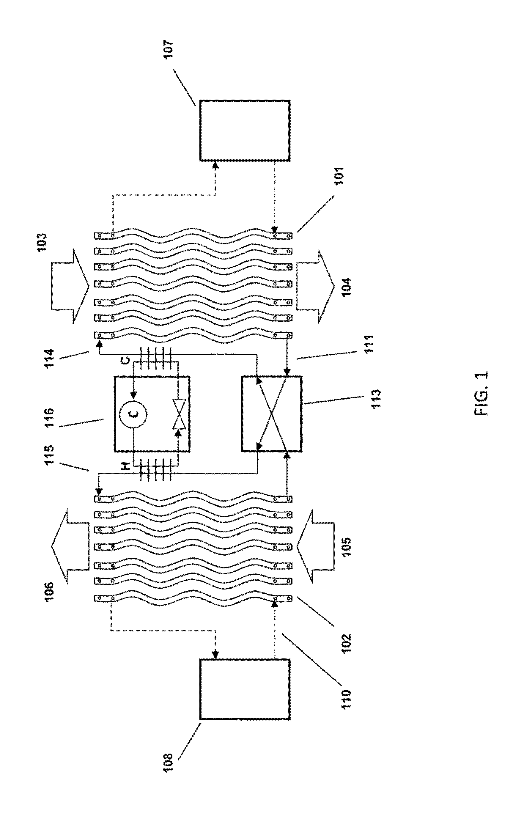
[0029]FIG. 1 depicts a new type of liquid desiccant system as described in more detail in U.S. Patent Application Publication No. US 20120125020, which is incorporated by reference herein. A conditioner 101 comprises a set of plate structures that are internally hollow. A cold heat transfer fluid is generated in cold source 107 and entered into the plates. Liquid desiccant solution at 114 is brought onto the outer surface of the plates and runs down the outer surface of each of the plates. The liquid desiccant runs behind a thin membrane that is located between the air flow and the surface of the plates. Outside air 103 is now blown through the set of wavy plates. The liquid desiccant on the surface of the plates attracts the water vapor in the air flow and the cooling water inside the plates helps to inhibit the air temperature from rising. The treated air 104 is put into a building space.
[0030]The liquid desiccant is collected at the bottom of the wavy plates at 111 and is transpo...
PUM
 Abstract
Description
Claims
Application Information
 - R&D
- Intellectual Property
- Life Sciences
- Materials
- Tech Scout
- Unparalleled Data Quality
- Higher Quality Content
- 60% Fewer Hallucinations
Browse by: Latest US Patents, China's latest patents, Technical Efficacy Thesaurus, Application Domain, Technology Topic, Popular Technical Reports.
© 2025 PatSnap. All rights reserved.Legal|Privacy policy|Modern Slavery Act Transparency Statement|Sitemap|About US| Contact US: help@patsnap.com


