
Pedal and cleat assembly

a technology of which is applied in the direction of vehicle cranks, mechanical devices, vehicle components, etc., can solve the problems of high load and high friction, high stress on the contact surface of the cleat and cleat assembly, and dangerous situation for the rider, etc., to achieve reliable and ready engagement, high stress, and high load

Active Publication Date: 2014-09-18
WAHOO FITNESS LLC
View PDF6 Cites 5 Cited by
  • Summary
  • Abstract
  • Description
  • Claims
  • Application Information

AI Technical Summary

Benefits of technology

The patent describes a way to make cleats and pedals that can easily engage and release without causing high friction or wear and tear. Clipless pedals are often made with small cleats that are under high stress and can easily seize to the contacting surfaces of the cleat and pedal, causing difficulty in disengaging. To solve this problem, the patent proposes using non-metallic or ceramic materials with high hardness, such as carbides, for the contacting surfaces. This reduces the likelihood of seizing and creates a safe and reliable engagement and release mechanism.

Problems solved by technology

Because the cleats are relatively small, the contacting surfaces of the cleat and pedal assemblies are under high stress, high load and high friction during use and during the engagement and release.
This, in turn, interferes with the rider's ability to disengage from the pedals, thereby creating a dangerous situation for the rider.

Method used


Image

  • Pedal and cleat assembly
  • Pedal and cleat assembly
  • Pedal and cleat assembly

Examples


Embodiment Construction

[0102]Specific, non-limiting embodiments of the present invention will now be described with reference to the drawings. It should be understood that such embodiments are by way of example only and merely illustrative of but a small number of embodiments within the scope of the present invention. Various changes and modifications obvious to one skilled in the art to which the present invention pertains are deemed to be within the spirit, scope and contemplation of the present invention as further defined in the appended claims.

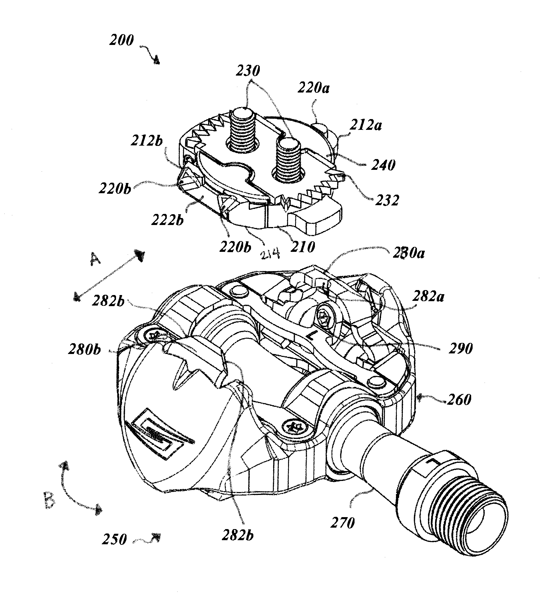
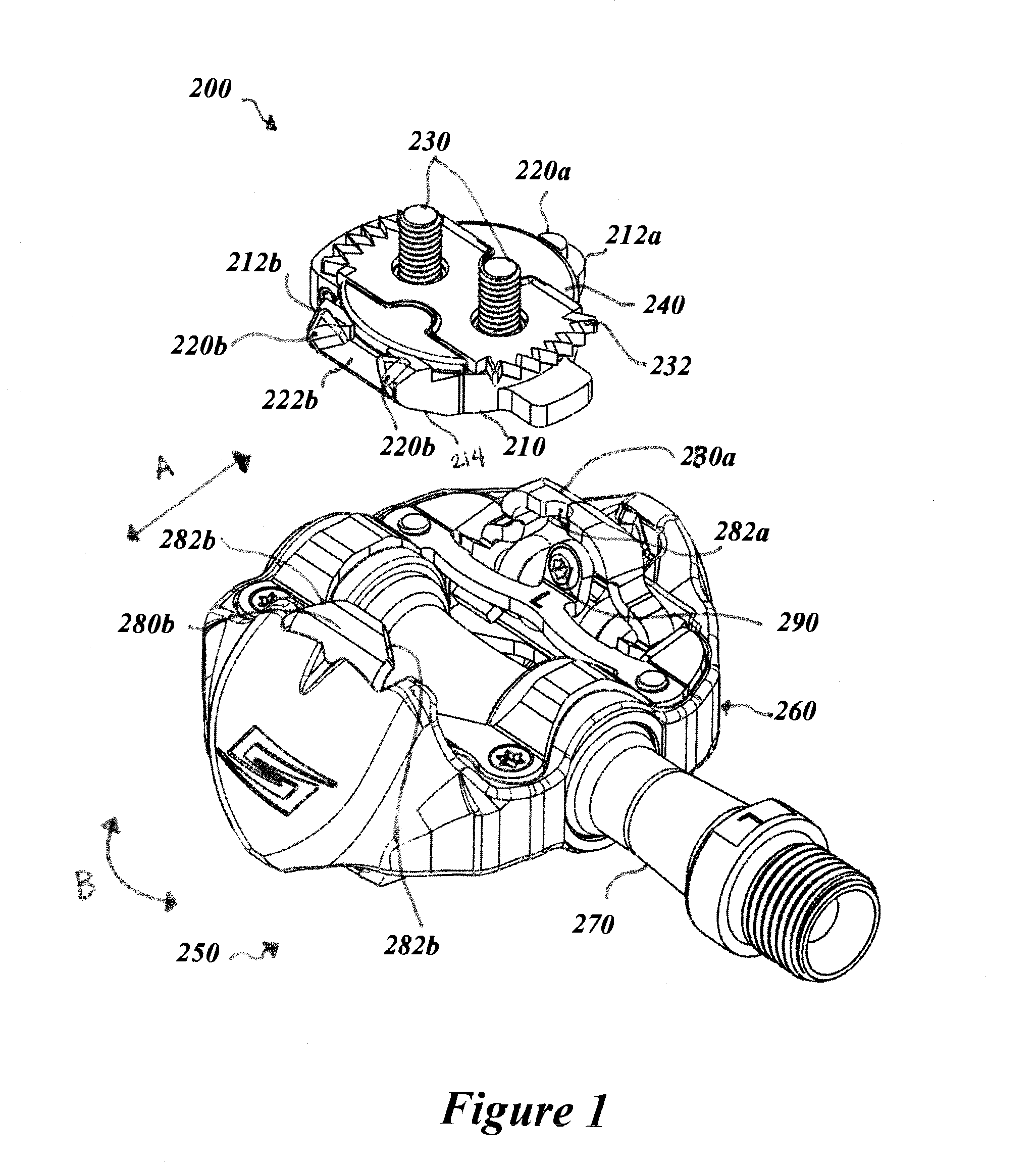
[0103]With reference now to the illustrative drawings, various embodiments of a bicycle pedal and cleat assembly are described and shown. The cleat assemblies described herein are designed to be secured to the underside of the sole of a rider's shoe (not shown), and are configured to be attachable to a double- or multi-sided pedal assembly. Because the pedal assembly is accessible from either one of the opposing sides (e.g., double-sided or multi-sided), the cl...


PUM


Abstract

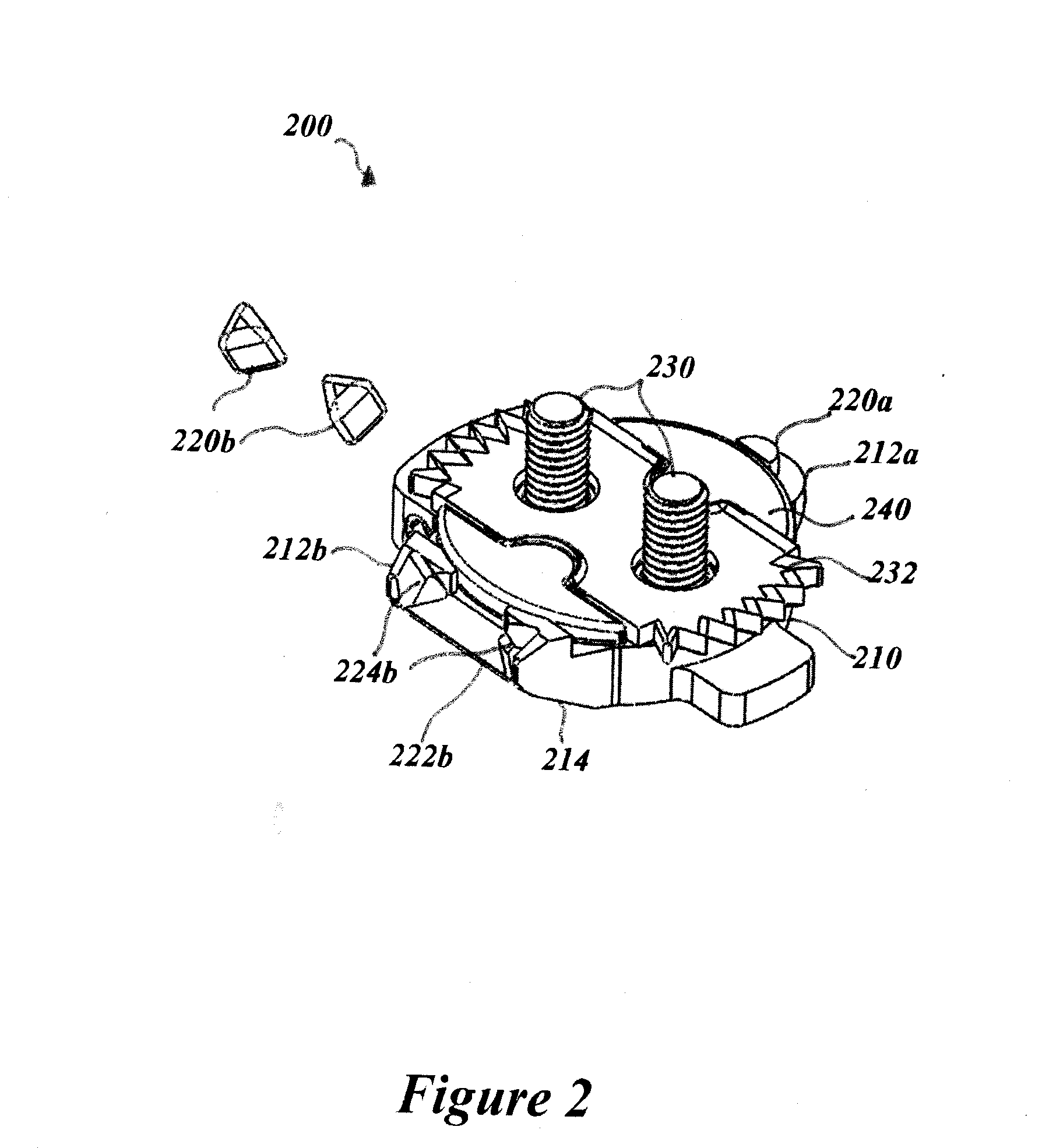
A pedal and cleat assembly comprises a pedal body having a first end and a second end, a first retainer mounted proximate the first end of the pedal body, and a second retainer mounted proximate the second end of the pedal body. The cleat assembly is configured to be releaseably coupled to the pedal assembly and comprises a cleat body having at least one coupling area, and at least one element shaped to be maintained within or disposed on the coupling area. The at least one coupling area is positioned at a forward or rearward end of the cleat body so that the at least one element can act as a cam surface against the first or second retainer. The at least one element is configured to rotate or articulate when maintained within or disposed on the coupling area to facilitate releasing the cleat assembly from the pedal assembly.

Description

CROSS REFERENCE TO RELATED APPLICATION[0001]This is a continuation-in-part of U.S. application Ser. No. 13 / 828,782, filed on Mar. 14, 2013, the entire contents of which are herein incorporated by reference.FIELD OF THE INVENTION[0002]This invention relates generally to an improved pedal and cleat assembly and, more particularly, to pedal and cleat assemblies incorporating features which permit the ready engagement and release of the pedal and cleat under a variety of environmental conditions.BACKGROUND[0003]Clipless pedals (also known as “clip-in” or “step-in” pedals) require a cleat fitted to the sole of a rider's shoe, which locks to the pedal and thus holds the shoe firmly to the pedal. Clipless pedals take a variety of forms and are typically adapted for the demands of a particular type of cycling, such as road cycling and off-road or mountain biking.[0004]Among the myriad of features desired for clipless pedals, the ability to readily engage the cleat to the pedal and to subseq...

Claims


Application Information

Patent Timeline
IPC IPC(8): B62M3/08
CPCB62M3/086Y10T74/217
Inventor BRYNE, RICHARD M.
Owner WAHOO FITNESS LLC
Learn More