Automated film pickup and placement method for insulating glass units

a technology of insulating glass and film pickup, which is applied in the direction of pile separation, transportation and packaging, manufacturing tools, etc., can solve the problems of unusable applications, high energy consumption, and inability to maintain the interior temperature of the structure at a comfortable temperature for the average human in standard attir

Inactive Publication Date: 2014-09-18
SOUTHWALL TECH INC
View PDF3 Cites 8 Cited by
  • Summary
  • Abstract
  • Description
  • Claims
  • Application Information

AI Technical Summary

Problems solved by technology

Whether cooling or heating, the desire to maintain the interior temperature of a structure at a temperature comfortable for the average human in standard attire can be very energy intensive.
While these products work very well from an insulation perspective, they suffer from a couple of major drawbacks.
This can make the windows more expensive to manufacture and to transport as well as making them unusable for some types of applications, such as large office towers.
Thus, while double-pane windows have become near ubiquitous, triple-pane windows are rare and quadruple-pane windows are almost unheard of.
PIB is tacky and can, therefore, temporarily fasten the film or glass to the spacer.
However, applying the film so that it is taut during assembly to the spacers and keeping it taut is generally impossible.
However, for the thermal shrinking to work well, the film still needs to be relatively flat in the IGU to begin with.
Currently, this is done by hand as the film can be difficult to handle and, since it is being attached to an adhesive, a missed positioning can result in a damaged product or a fold or wrinkle that cannot be easily removed and that thermal shrinking cannot correct.
Further, since each piece of film can be different, and cut from a different position from an unrolling roll of film, there is no standardization from one IGU to the next in construction making the process difficult for automation.

Method used


Image

  • Automated film pickup and placement method for insulating glass units
  • Automated film pickup and placement method for insulating glass units
  • Automated film pickup and placement method for insulating glass units

Examples


Embodiment Construction

)

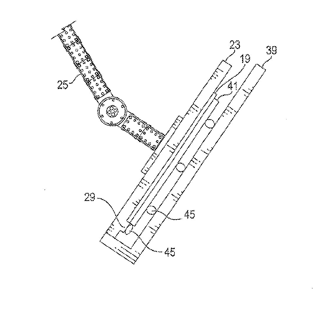
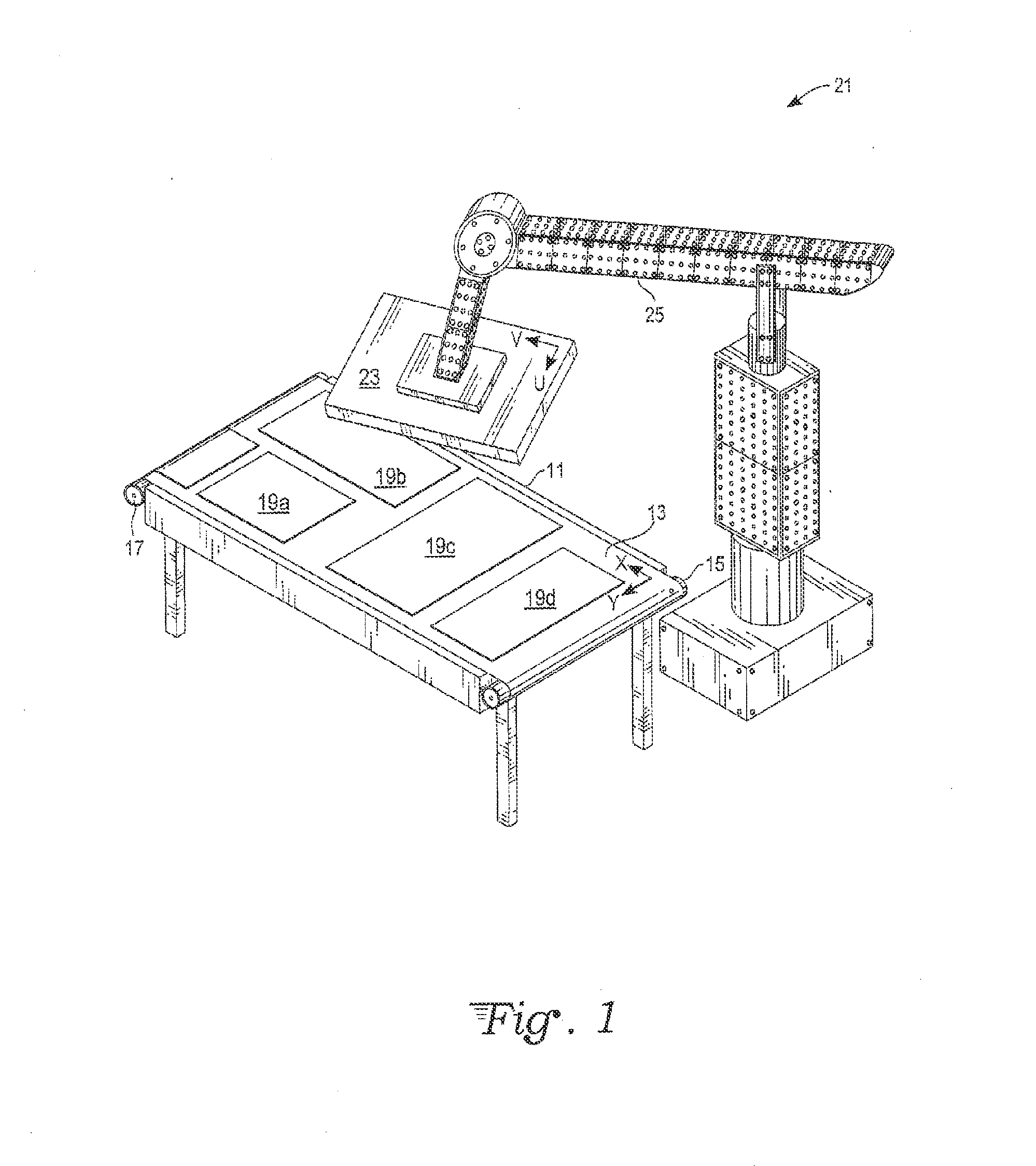
[0043]The systems and methods discussed herein are designed, in an embodiment, to pick up a sheet of flexible film or other thin generally planar material, where the sheet is of a size that can vary with each pickup, match that sheet to a frame of matching size, orient the sheet to the frame, and position it on an adhesive which is towards the periphery of the frame in a generally planar arrangement. As shown in the FIGS., the method generally begins with identifying a position and orientation of a specified sheet (19a) from a roll (15) including multiple sheets (19a)-(19d) on a cutting table (11) and moving a robotic sheet pickup apparatus (21) to a corresponding position to that identified for the sheet (19a).

[0044]An edge of the specified sheet (19a) is lifted off of the table (11), beginning with mechanical suction that brings a corner of the sheet (19a) to within proximity of a primary vacuum suction of the pickup apparatus (21) allowing it to be grabbed by the vacuum suction....


PUM

PropertyMeasurementUnit
temperatureaaaaaaaaaa
sizeaaaaaaaaaa
flexibleaaaaaaaaaa

Abstract

A method of automatically mounting a sheet from a cutting table onto a spacer frame of an insulating glass unit begins with identifying a position and orientation of a specified sheet on the cutting table and moving a robotic sheet pickup apparatus to a corresponding position to that identified for the sheet. An edge of the specified sheet is lifted off of the table, beginning with mechanical suction that brings a corner of the sheet to within proximity of a primary vacuum suction of the pickup apparatus. In particular, the pickup apparatus may have a substantially planar platen with a set of channels coupled to a vacuum source. Once the sheet is fully picked up by vacuum suction, the sheet is laid upon a top surface of a tilt table, which can be simply the platen inverted. The table (or platen) is tilted to bring a corner of the sheet to abut against physical fences. Once the position and orientation of the sheet is so known, the sheet is oriented to correspond to a frame, and attached thereto.

Description

BACKGROUND[0001]1. Field of the Invention[0002]The present invention relates generally to the operation of automated or robotic assembly equipment, especially for the manufacturing of windows, and in particular to any such equipment adapted for pickup of sheets, panels, films, webs or laminates of various sizes at a first location and the placement or attachment of such material at a desired second location, such as to frames of multi-pane insulating glass units (IGUs).[0003]2. Description of the Related Art[0004]As the cost of fossil fuels and other energy sources continues to rise and people become more concerned with the impact that energy generation has on the environment, there has been an increased interest in energy conservation. Products which themselves are not responsible for energy consumption, but which have an effect on the energy consumption of other devices, are in increased demand.[0005]In architectural structures, generally the most energy demanding activity is clim...

Claims


Application Information

Patent Timeline
Patent Type & Authority Applications(United States)
IPC IPC(8): B65H5/08B25J11/00B25J15/06B65H9/04
CPCB65H5/08B65H9/04B25J15/0616B25J11/00B65G49/068E06B3/6715E06B3/67386B65G49/067
Inventor SAWATZKY, VONNENGBERSEN, TOMSTOESSEL, CHRISTIAN H.PATEL, KAYUR A.CARGILL, MARKSALINAS, JR., CARLOS
Owner SOUTHWALL TECH INC
Why Eureka
Try Eureka