
Low-power architectural covering

a low-power, architectural technology, applied in the direction of door/window protective devices, wing accessories, sustainable buildings, etc., can solve the problems of high self-generated noise, inadequate battery life, and battery-powered systems

Active Publication Date: 2014-09-18
THE WATT STOPPER
View PDF7 Cites 31 Cited by
  • Summary
  • Abstract
  • Description
  • Claims
  • Application Information

AI Technical Summary

Benefits of technology

The present invention relates to an architectural covering that includes a shade material, a motor, a shaft, a power supply unit, a controller unit, a rotation detector, and an encoder unit. The motor is connected to the shade material and can move it by its rotation. The rotation detector can detect the rotation of the motor and send a signal to the controller unit. The controller unit can switch between an awake state and an asleep state and power the encoder unit when the shatch moves. The rotation detector includes a Hall Effect sensor positioned adjacent to the magnetic device that causes rotation of the sh weiteren. This invention allows for the continuous and precise tracking of the motor's movement and ensures smooth operation of the architectural covering.

Problems solved by technology

Unfortunately, these battery-powered systems suffer from many drawbacks, including, for example, high levels of self-generated noise, inadequate battery life, inadequate or nonexistent counterbalancing capability, inadequate or nonexistent manual operation capability, inconvenient installation requirements, and the like.
Another problem in the industry is that many motorized window shades do not allow for manual movement.
That is, when the motorization components are added to a window shade the window shade can no longer be moved by hand.
While the functionality of motorized shades was an added advantage, an unforeseen problem arose when patrons of the hotel, who were unaware that the shades were movable only by way of motorization, attempted to open or close the shades manually.
This manual movement would break the internal gears of the shades requiring replacement at great inconvenience and cost.
This breakage is a result of the arrangement where the motor is designed to rotate fast requiring a substantial gear reduction.
This substantial gear reduction causes a great amount of back drive in the motor when someone tugs on it in an attempt to make it manually move which causes the gears to break.

Method used


Image

  • Low-power architectural covering
  • Low-power architectural covering
  • Low-power architectural covering

Examples


Embodiment Construction

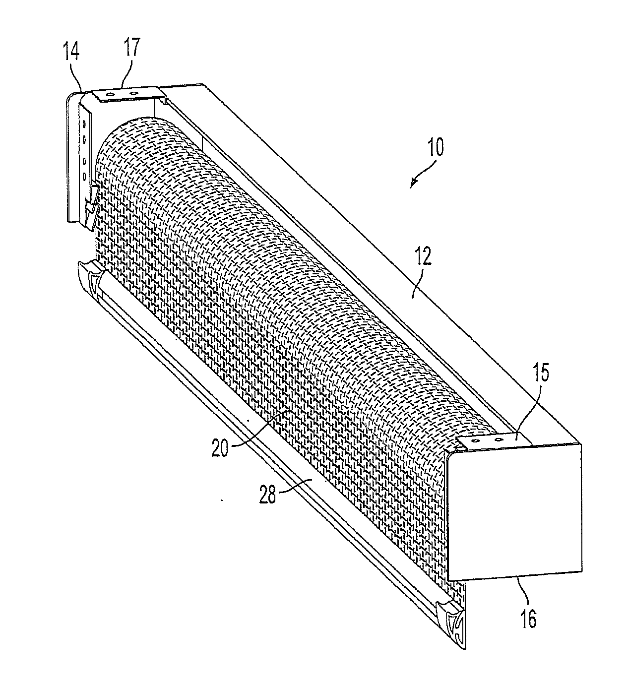
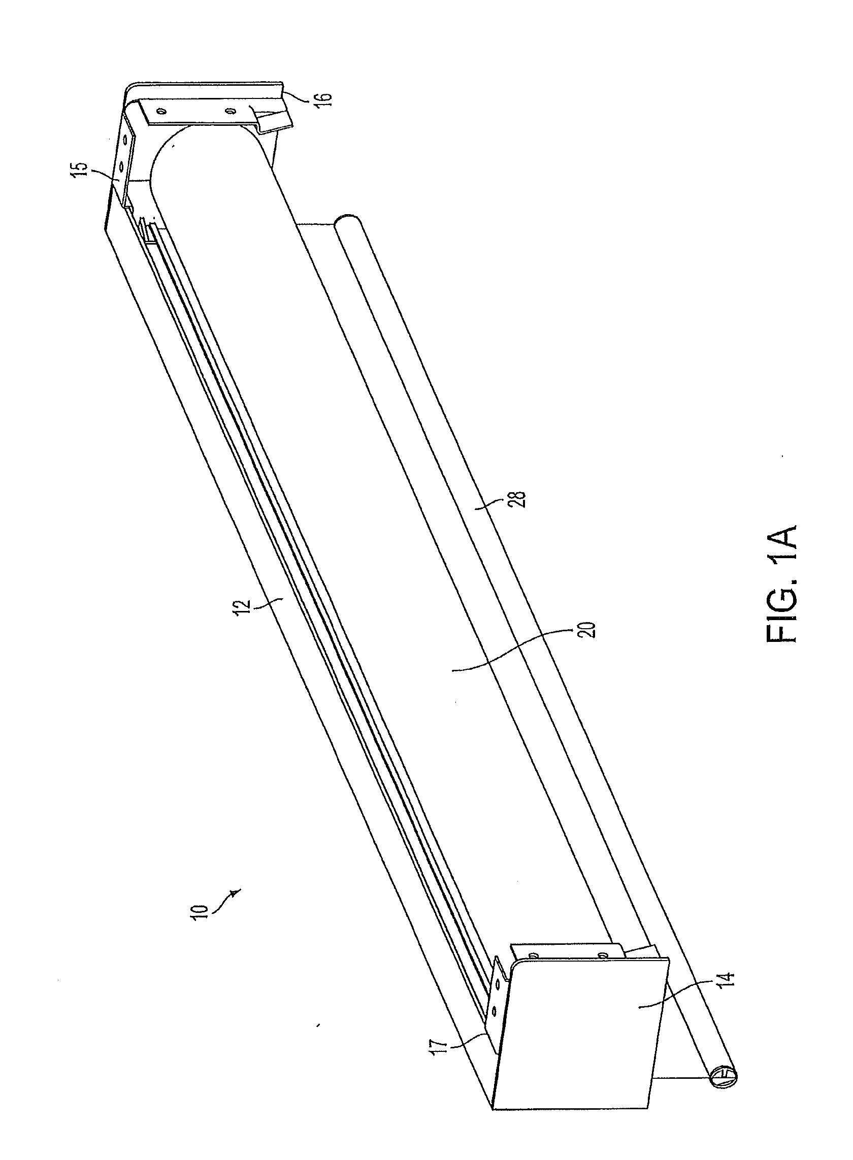
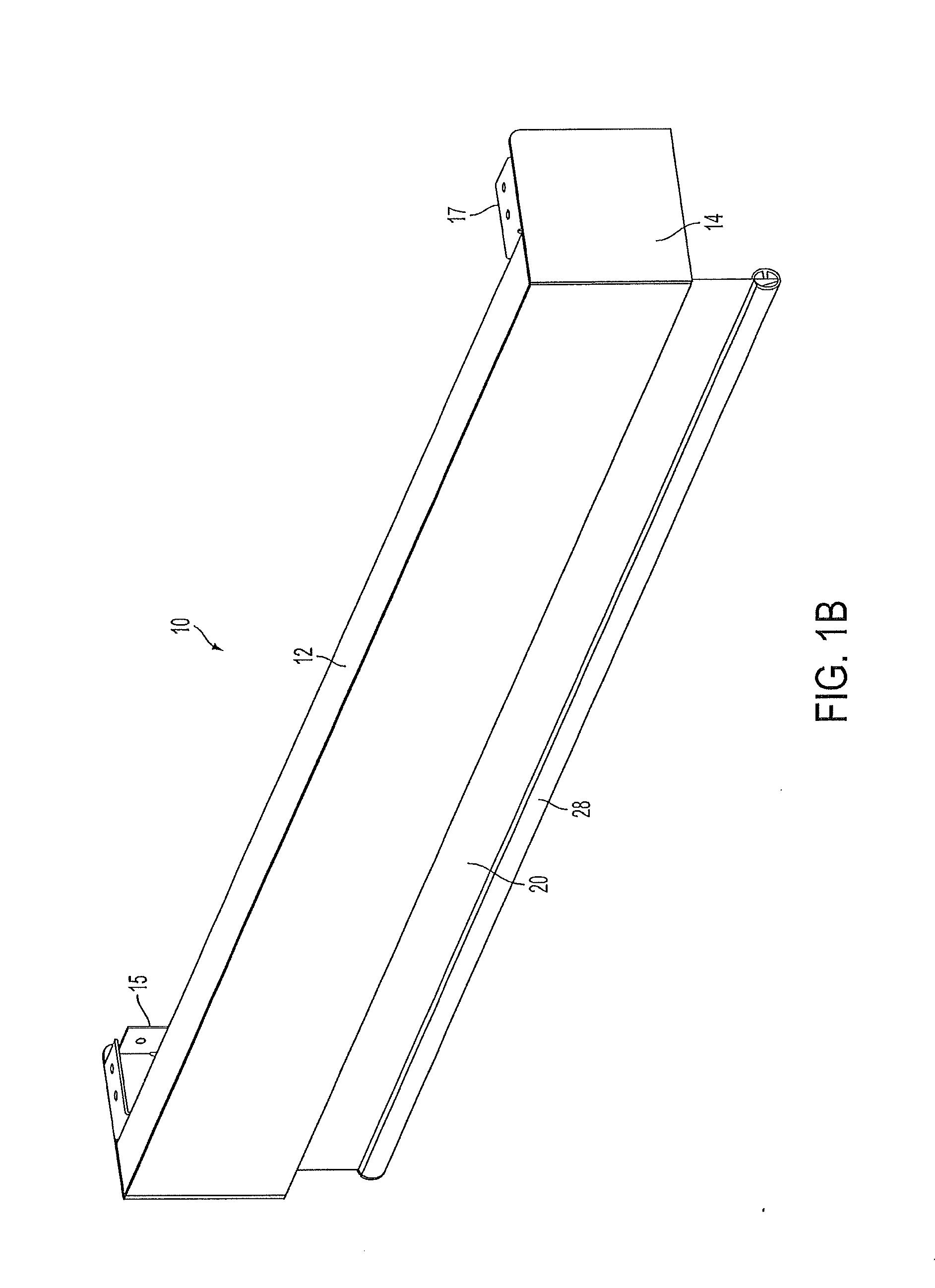
[0076]The invention will now be described with reference to the drawing figures, in which like reference numerals refer to like parts throughout. The term “shade” as used herein describes any flexible material, such as a shade, a curtain, a screen, etc., that can be deployed from, and retrieved onto, a storage tube.

[0077]Embodiments of the present invention provide an architectural covering, such as a motorized roller shade in which the batteries, DC gear motor, control circuitry are entirely contained within a shade tube that is supported by bearings. Two support shafts are attached to respective mounting brackets, and the bearings rotatably couple the shade tube to each support shaft. The output shaft of the DC gear motor is fixed to one of the support shafts, while the DC gear motor housing is mechanically coupled to the shade tube. Accordingly, operation of the DC gear motor causes the motor housing to rotate about the fixed DC gear motor output shaft, which causes the shade tub...


PUM


Abstract

An architectural covering is provided. The architectural covering includes: shade material; the shade material operatively connected to a motor unit such that movement of the motor unit causes movement of the shade material; the motor unit comprising a DC motor and a shaft connected to the DC motor; a power supply unit electrically connected to the motor unit; a controller unit electrically connected to the motor unit, the controller unit having a microprocessor; and a rotation detector configured to detect rotation of the motor unit and upon detection of rotation of the motor unit transmit a signal to the microprocessor, wherein the microprocessor of the controller unit is configured to power an encoder unit in response to determination of manual movement of the shade material. A motor and control unit for an architectural covering may be provided.

Description

CROSS-REFERENCE TO RELATED APPLICATIONS[0001]This application claims priority to pending provisional application No. 61 / 811,650, titled, Low-Power Architectural Covering, filed Apr. 12, 2013. This application also is a continuation-in-part, of pending U.S. patent application Ser. No. 13 / 921,950, entitled, Motorized Shade with the Transmission Wire Passing Through the Support Shaft, filed Jun. 19, 2013, which is a continuation-in-part of pending application Ser. No. 13 / 847,607 filed on Mar. 20, 2013, which is a continuation of application Ser. No. 13 / 276,963, filed on Oct. 19, 2011, now U.S. Pat. No. 8,659,246, which is a continuation-in-part of application Ser. No. 12 / 711,192, filed on Feb. 23, 2010, now U.S. Pat. No. 8,299,734. This application is also a continuation-in-part of pending application Ser. No. 13 / 771,994, filed on Feb. 20, 2013, titled High Efficiency Roller Shade and Method For Setting Artificial Stops, which is a continuation-in-part of application Ser. No. 13 / 653,45...

Claims


Application Information

Patent Timeline
Patent Type & Authority Applications(United States)
IPC IPC(8): E06B9/68E06B9/56E06B9/42
CPCE06B9/42E06B2009/6818E06B9/40E06B2009/6872E06B9/62E06B9/72E06B2009/2476E06B9/50Y02B80/00Y02A30/24E06B9/44E06B9/68E06B2009/6809E06B2009/6845
Inventor MULLET, WILLIS JAYKIRKLAND, MATTHEW WARRENGEAN, RICHARDROSENMARKLE, STEVEN T.
Owner THE WATT STOPPER
Learn More