Twisted conduit for geothermal heat exchange

a geothermal heat exchange and conduit technology, applied in geothermal energy generation, lighting and heating apparatus, heat production devices, etc., can solve the problem that the most desired or preferred approach to heat exchange is not necessarily the minimum diameter borehole, and achieves the effect of convenient storage, transportation, installation and thermal transfer efficiency, and convenient uncoiled and inserted

Active Publication Date: 2014-09-18
JENSEN ROBERT
View PDF3 Cites 17 Cited by
  • Summary
  • Abstract
  • Description
  • Claims
  • Application Information

AI Technical Summary

Benefits of technology

[0014]The present disclosure is a novel structure of a geothermal heat exchange apparatus that facilitates the ease of storage, transportation, installation and thermal transfer efficiency. Specifically, the geothermal heat exchange apparatus includes the twisting of a plurality of pipes onto a central conduit in a compact minimum diameter form that can be readily uncoiled and inserted into a borehole. It is understood that while it is preferred in general to minimize the diameter of the borehole, there are applications in which the minimum diameter borehole is not necessarily the most desired or preferred approach for heat exchange. It is understood that it can be desirable to drill the borehole to a desired diameter vice the minimum diameter for the installation of the compact geothermal heat exchange apparatus. The structure of the geothermal heat exchange apparatus makes more efficient use of the borehole space by placing more pipe into the borehole in a compact spaced arrangement for heat transfer. The unique structural arrangement of the geothermal heat exchange apparatus creates additional surface area for heat transfer surface through flexible thin walled pipes in a small diameter borehole. The twisted plurality of pipes is wrapped in helical arrangement that is in contact with the center conduit such that the interface between the plurality of pipes and the central conduit bind the plurality of pipes in position on the central conduit. This structural arrangement also provides support for retaining the relative position of each pipe during installation in a relatively tight borehole. The flexible nature of the conduit and the plurality of pipes in a twisted arrangement is easily coiled and transported in a roll to a job site.

Problems solved by technology

It is understood that while it is preferred in general to minimize the diameter of the borehole, there are applications in which the minimum diameter borehole is not necessarily the most desired or preferred approach for heat exchange.

Method used


Image

  • Twisted conduit for geothermal heat exchange
  • Twisted conduit for geothermal heat exchange
  • Twisted conduit for geothermal heat exchange

Examples


Embodiment Construction

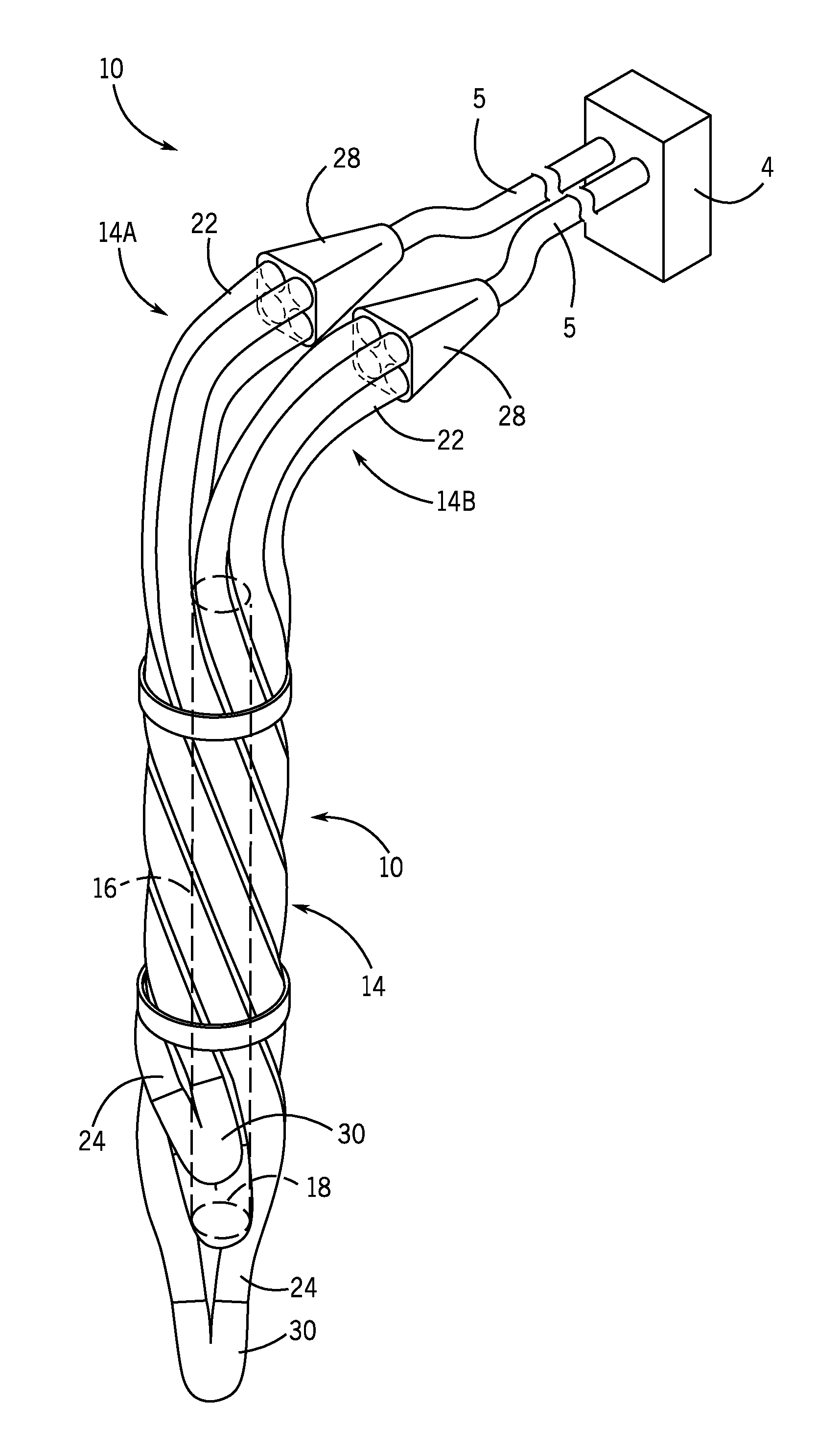
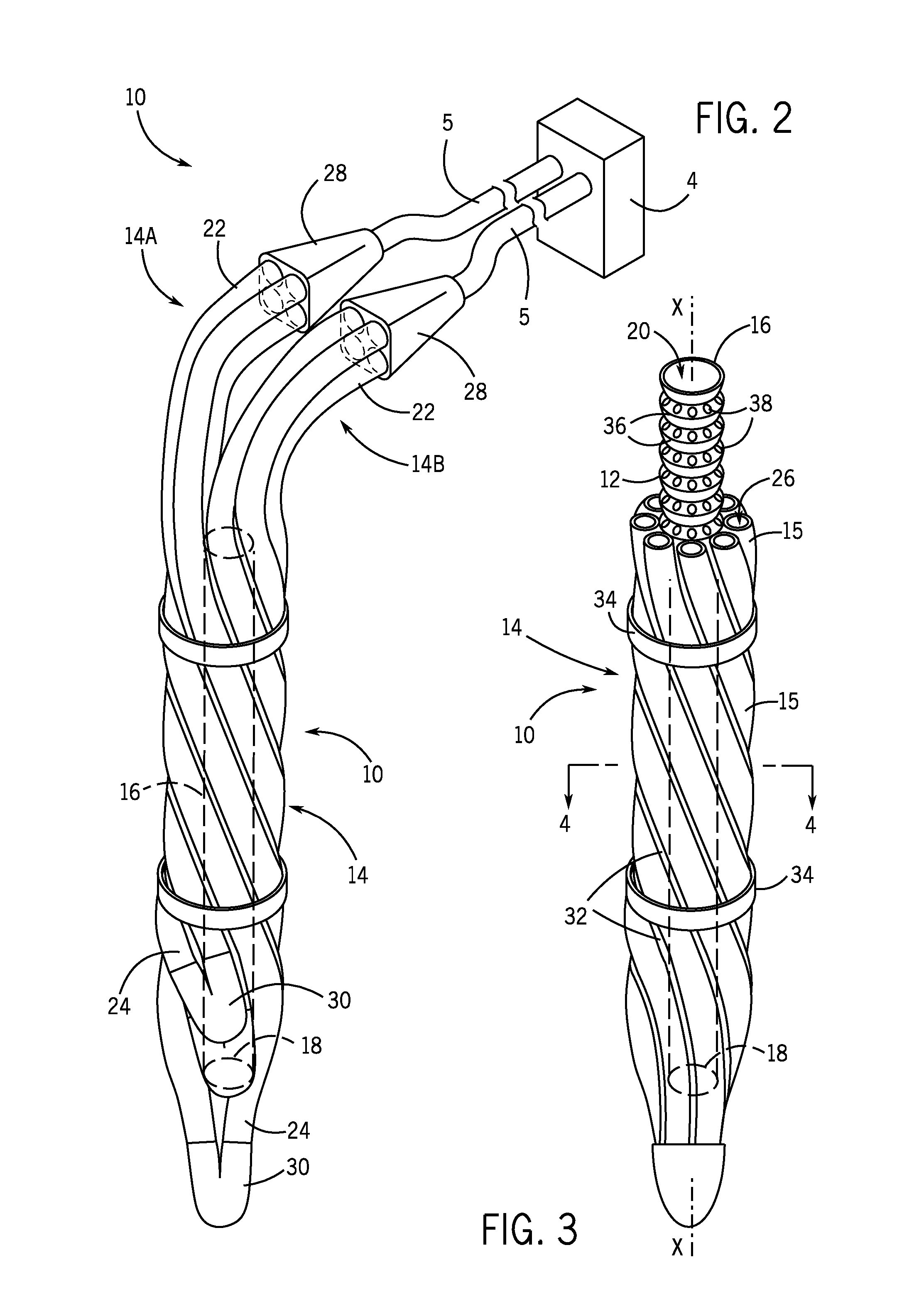
[0028]Referring initially to FIG. 2, a geothermal heat exchange apparatus 10 includes a center conduit 12 and a plurality of pipes 14. The plurality of pipes 14 is positioned in a twisted arrangement on center conduit 12. Geothermal heat exchange apparatus 10 defines a first longitudinal axis-X aligned with a centerline of central conduit 12.

[0029]Center conduit or conduit 12 has a flexible tubular structure that includes a first end portion 16 and an opposed second end portion 18. The tubular wall of conduit 12 defines an aperture 20 that is a through hole that extends between first end portion 16 and second end portion 18. Aperture 20 has a first inside diameter. In one preferred embodiment, the corrugated center conduit 12 dimensions include an inside diameter of approximately 1.9 inches, outside diameter of approximately 2.375 inches and a wall thickness of approximately 1 / 16th or 0.0625 inches. It is understood that the size of the inside diameter can vary depending upon the in...


PUM


Abstract

A geothermal heat exchange apparatus is disclosed that comprises a flexible assembly of a plurality of pipes twisted on a central conduit. The central conduit has a tubular structure. The plurality of pipes is twisted around the central conduit. The plurality of pipes is adapted to connect to an external environmental control system that supplies a heat exchange liquid for the transfer of heat through the plurality of pipes. The geothermal heat exchange apparatus is adapted for positioning in a hole in the earth for the exchange of heat.

Description

CROSS-REFERENCE TO RELATED APPLICATIONS[0001]This application claims priority to and is a continuation in part of U.S. patent application Ser. No. 13 / 385,378 filed Feb. 16, 2012 that is a continuation-in-part of U.S. patent application Ser. No. 12 / 660,226 filed Feb. 23, 2010 and U.S. patent application Ser. No. 13 / 385,383 filed Feb. 16, 2012 that is a continuation-in-part of U.S. patent application Ser. No. 12 / 660,225 filed Feb. 23, 2010, the disclosures of which are incorporated by reference herein and made a part of this application.BACKGROUND OF THE INVENTION[0002]1. Field of the Invention[0003]The present invention relates to the arrangement of pipes for geothermal heat exchange and in particular to arrangements of a plurality of pipes twisted onto a central conduit for geothermal heat exchange.[0004]2. Description of the Related Art[0005]Geothermal heat exchange structures are well known and include a broad array of configurations for the exchange of heat between an environment...

Claims


Application Information

Patent Timeline
Patent Type & Authority Applications(United States)
IPC IPC(8): F24J3/08
CPCF24J3/083F24T10/15Y02E10/10
Inventor JENSEN, ROBERT
Owner JENSEN ROBERT
Why Eureka
Try Eureka