Apparatuses and related methods for modulating power of a wireless power receiver

a wireless power receiver and receiver technology, applied in adaptive control, process and machine control, instruments, etc., can solve the problems of inconvenient charging, cramped charging area, and space occupation of the cord extending between the power source and the battery-powered devi

Active Publication Date: 2014-09-18
INTEGRATED DEVICE TECH INC
View PDF6 Cites 50 Cited by
  • Summary
  • Abstract
  • Description
  • Claims
  • Application Information

AI Technical Summary

Problems solved by technology

The cord extending between the power source and the battery-powered device can take up space.
In situations where multiple devices require charging, each with their own charger and cord, the charging area can become cramped and inconvenient.

Method used


Image

  • Apparatuses and related methods for modulating power of a wireless power receiver
  • Apparatuses and related methods for modulating power of a wireless power receiver
  • Apparatuses and related methods for modulating power of a wireless power receiver

Examples


Embodiment Construction

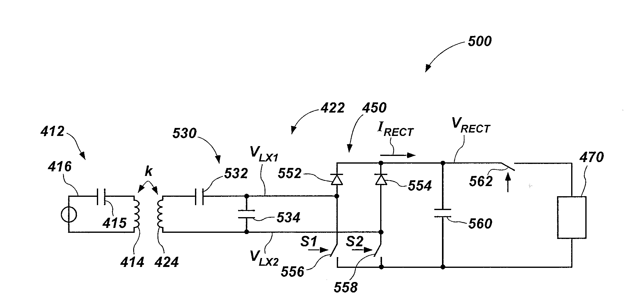
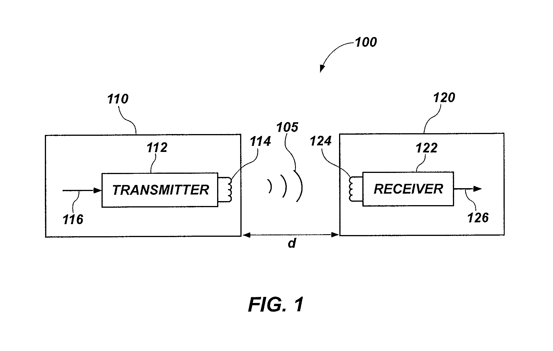
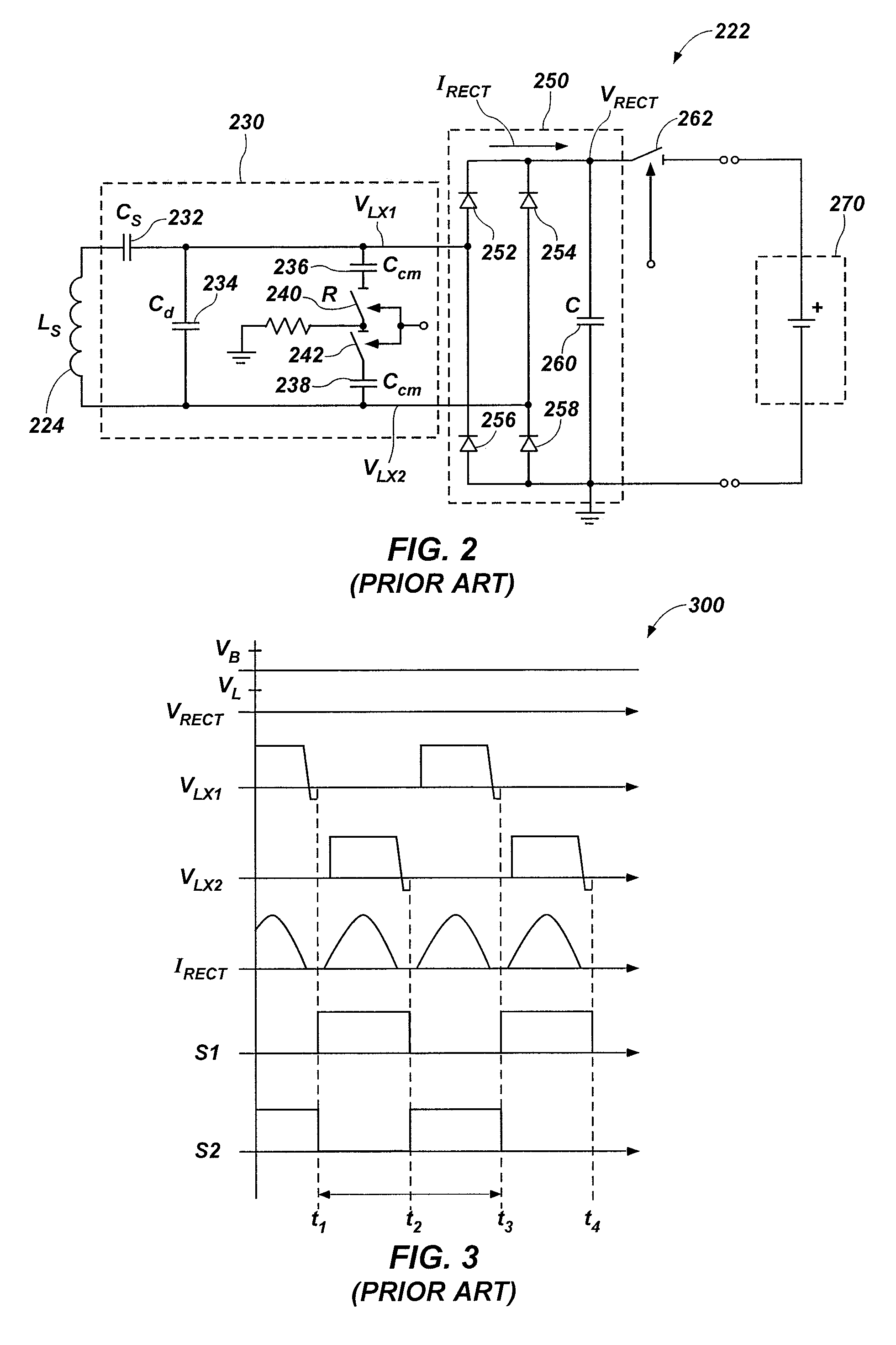
[0017]In the following description, reference is made to the accompanying drawings in which is shown, by way of illustration, specific embodiments of the present disclosure. Other embodiments may be utilized and changes may be made without departing from the scope of the disclosure. The following detailed description is not to be taken in a limiting sense, and the scope of the present invention is defined only by the appended claims.

[0018]Furthermore, specific implementations shown and described are only examples and should not be construed as the only way to implement or partition the present disclosure into functional elements unless specified otherwise herein. It will be readily apparent to one of ordinary skill in the art that the various embodiments of the present disclosure may be practiced by numerous other partitioning solutions.

[0019]In the following description, elements, circuits, and functions may be shown in block diagram form in order not to obscure the present disclos...


PUM


Abstract

A wireless power enabled apparatus may comprise a wireless power receiver that includes a receive coil configured to generate an AC signal responsive an electromagnetic field, a rectifier including a plurality of switches configured to receive the AC signal and generate an output power signal, and control logic configured to control the plurality of switches to cause the rectifier to modulate the output power signal. The control logic may be configured to control the plurality of switches within the rectifier to have an overlap delay that modulates at least one parameter of the wireless power receiver. A method of operating a receiver side of a wireless power transfer system comprises generating an output power signal including a rectified voltage and a rectified current responsive to receiving a wireless power signal, and controlling a rectifier according to at least one mode including a power modulation mode modulating the output power signal.

Description

FIELD[0001]Embodiments of the present disclosure relate generally to wireless power transfer and, more particularly, to apparatuses and related method for power modulation for wireless power receivers.BACKGROUND[0002]Battery-powered devices (e.g., consumer electronic devices, electric and hybrid automobiles, etc.) are charged from a power source (e.g., AC power outlet) through a charging device. The charging device couples the battery to the power source through an adaptor. The cord extending between the power source and the battery-powered device can take up space. In situations where multiple devices require charging, each with their own charger and cord, the charging area can become cramped and inconvenient.[0003]Approaches are being developed that use over-the-air or wireless power transmission between a transmitter and a receiver coupled to the electronic device. Wireless power transmission using inductive coils is one method considered as an un-tethered method for transferring...

Claims


Application Information

Patent Timeline
Patent Type & Authority Applications(United States)
IPC IPC(8): H02J7/02H04B5/00
CPCH04B5/0037H02J7/025H04B5/0031H02M7/219H02J50/12Y02B70/10H02J50/80H02J50/60G05B13/0205
Inventor BAKKER, ANTONLAMBERT, CRAIG
Owner INTEGRATED DEVICE TECH INC
Why Eureka
Try Eureka