Micro-Channel Heat Exchanger for Stator of Electrical Machine with Supply Header

a stator and microchannel technology, applied in the direction of dynamo-electric machines, electrical apparatus, magnetic circuit shapes/forms/construction, etc., can solve the problems of ac magnetic fields leading to losses in the magnetic steel supporting the windings and conductors in the stator, and generating heat through friction. , to achieve the effect of high film coefficient, reducing the pressure required to drive the flow, and high efficiency

Active Publication Date: 2014-09-18
BALDOR ELECTRIC COMPANY
View PDF4 Cites 24 Cited by
  • Summary
  • Abstract
  • Description
  • Claims
  • Application Information

AI Technical Summary

Benefits of technology

[0008]Accordingly, by routing fluid through the micro-channel heat exchanger formed in the stator, a mechanism for cooling the radially outward regions of the lamination stack that forms the stator is provided. Advantageously, the surface area of the micro-channel heat exchanger may be 1-2 orders of magnitude larger than the outer surface of the motor.

Problems solved by technology

Indeed, the physical interaction of the devices' various moving components produces heat by way of friction.
As yet another source of heat, AC magnetic fields lead to losses in the magnetic steel supporting the windings

Method used


Image

  • Micro-Channel Heat Exchanger for Stator of Electrical Machine with Supply Header
  • Micro-Channel Heat Exchanger for Stator of Electrical Machine with Supply Header
  • Micro-Channel Heat Exchanger for Stator of Electrical Machine with Supply Header

Examples


Embodiment Construction

[0041]As discussed in detail below, the embodiments provide apparatus and methods for cooling high power density electric machines having lamination stacks. Although the discussion focuses on electric motors and generators, these principles may also afford benefits to a number of applications in which the cooling of a lamination stack is a concern. Accordingly, the following discussion relates to exemplary embodiments and, as such, should not be viewed as limiting the appended claims to the embodiments described.

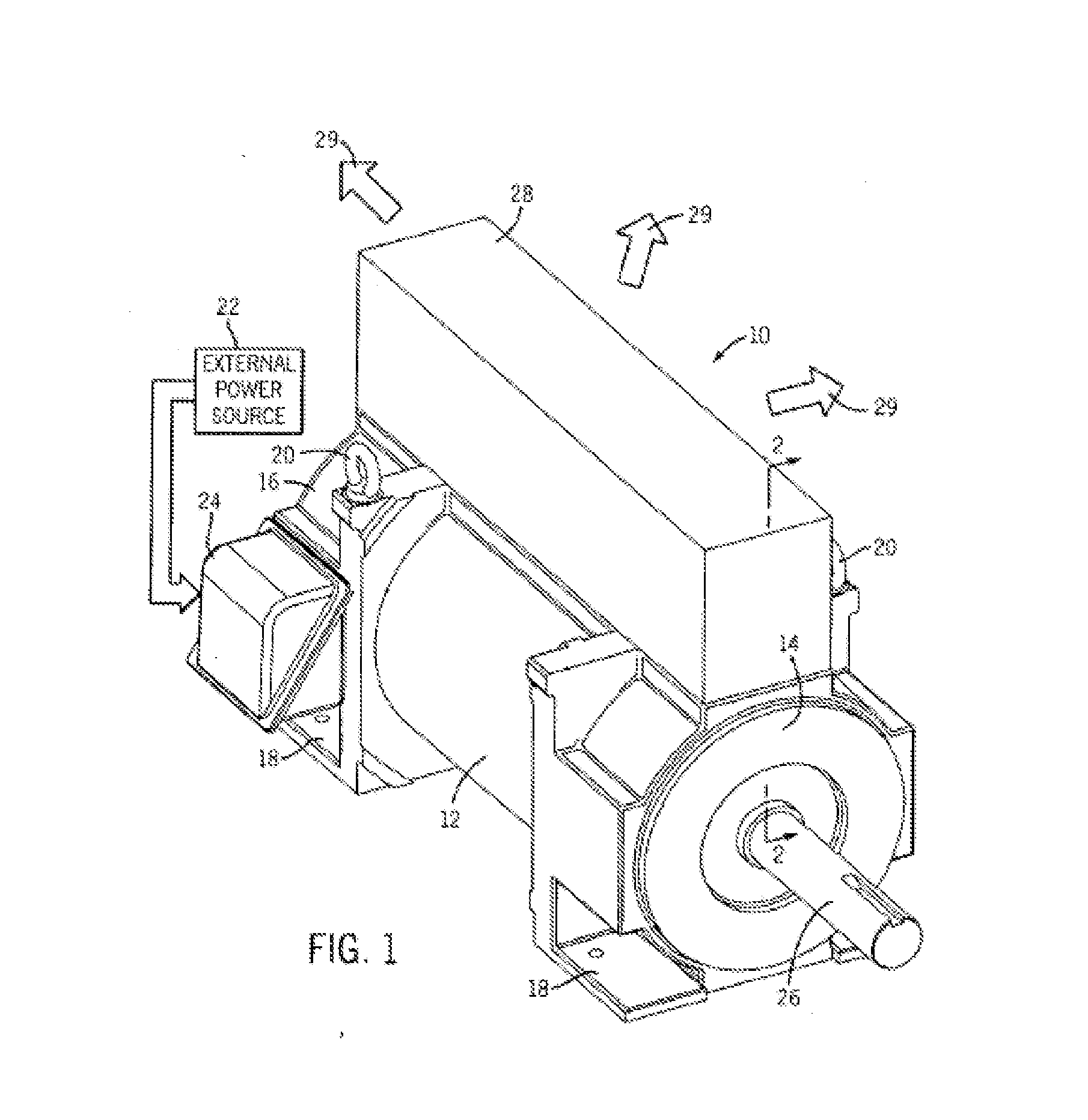
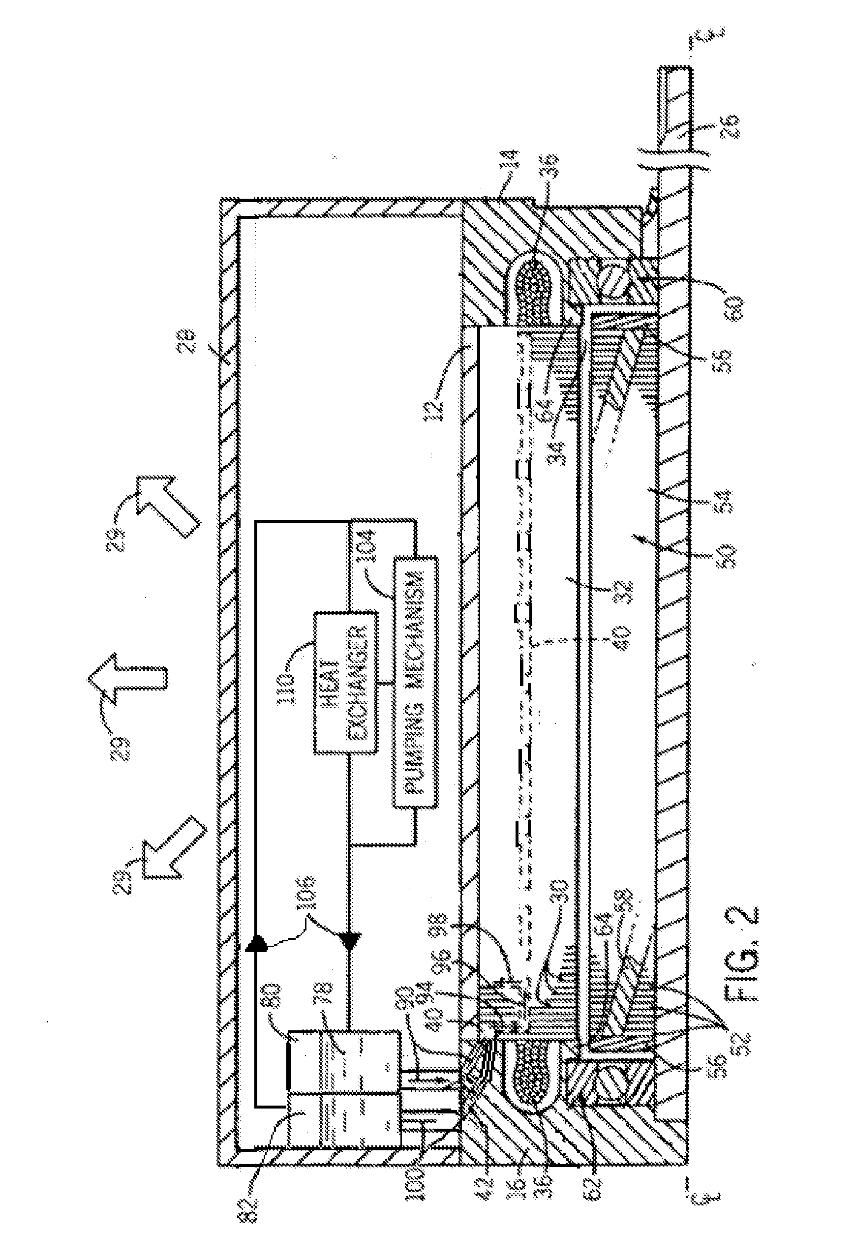
[0042]Turning to the drawings, FIG. 1 illustrates an exemplary electric motor 10. In the embodiment illustrated, the motor 10 comprises an induction motor housed in a motor housing. Although the drawings show an induction motor, the principles described herein may also be used in connection with other motor types. The exemplary motor 10 comprises a frame 12 capped at each end by drive-end and opposite drive-end endcaps 14,16, respectively. The frame 12 and the endcaps 14,16 ...


PUM


Abstract

An electric machine has a stator that comprises a plurality of laminations with teeth and cooling apertures about a central opening. When the laminations are stacked to form the stator core, the teeth of adjacent laminations cooperate to form slots disposed circumferentially about the central opening that are configured to receive a plurality of stator windings, and the cooling apertures angularly spaced about the central opening cooperate to form cooling manifolds that extend along a length of the stator core. A portion of the laminations has their cooling apertures offset from other laminations in the stack in a manner to create a plurality of flow paths transverse to the manifolds. The transverse flow paths extend angularly between laminations and adjacent manifolds. A header assembly directs flow into and out of the stator core.

Description

CROSS REFERENCE TO RELATED APPLICATIONS[0001]This application is a continuation-in-part to application Ser. No. 13 / 827,560, filed Mar. 14, 2013, the disclosure of which is incorporated by reference herein.STATEMENT REGARDING FEDERALLY SPONSORED RESEARCH OR DEVELOPMENT[0002]This invention was made with Government support under DE-AR0000191 awarded by DOE. The Government has certain rights in this invention.BACKGROUND AND SUMMARY[0003]This disclosure relates generally to the field of electric motors and generators, and to methods and apparatus for cooling such. For example, the disclosure discusses a technique for dissipating heat in motors and generators by routing fluid along internal surfaces of a stator core. Although the present discussion focuses on electric motors and generators, the present invention affords benefits to a number of applications related to lamination stacks and to the cooling of such stacks.[0004]During operation, conventional motors and generators generate hea...

Claims


Application Information

Patent Timeline
IPC IPC(8): H02K1/20
CPCH02K1/20H02K9/197
Inventor SHOYKHET, BORIS A.MEYER, ANDREAS A.SCHIFERL, RICHARD F.DONG, QIMINBRINKMANN, MICHAEL
Owner BALDOR ELECTRIC COMPANY
Why Eureka
Try Eureka