

Rigid LCD Assembly
a technology of liquid crystal display and assembly, which is applied in the direction of display means, instruments, vehicle components, etc., can solve the problems of difficult formation of thin components, high/low ambient temperature, and inability to withstand sunligh
- Summary
- Abstract
- Description
- Claims
- Application Information
AI Technical Summary
Benefits of technology
Problems solved by technology
Method used
Image

Examples
Embodiment Construction
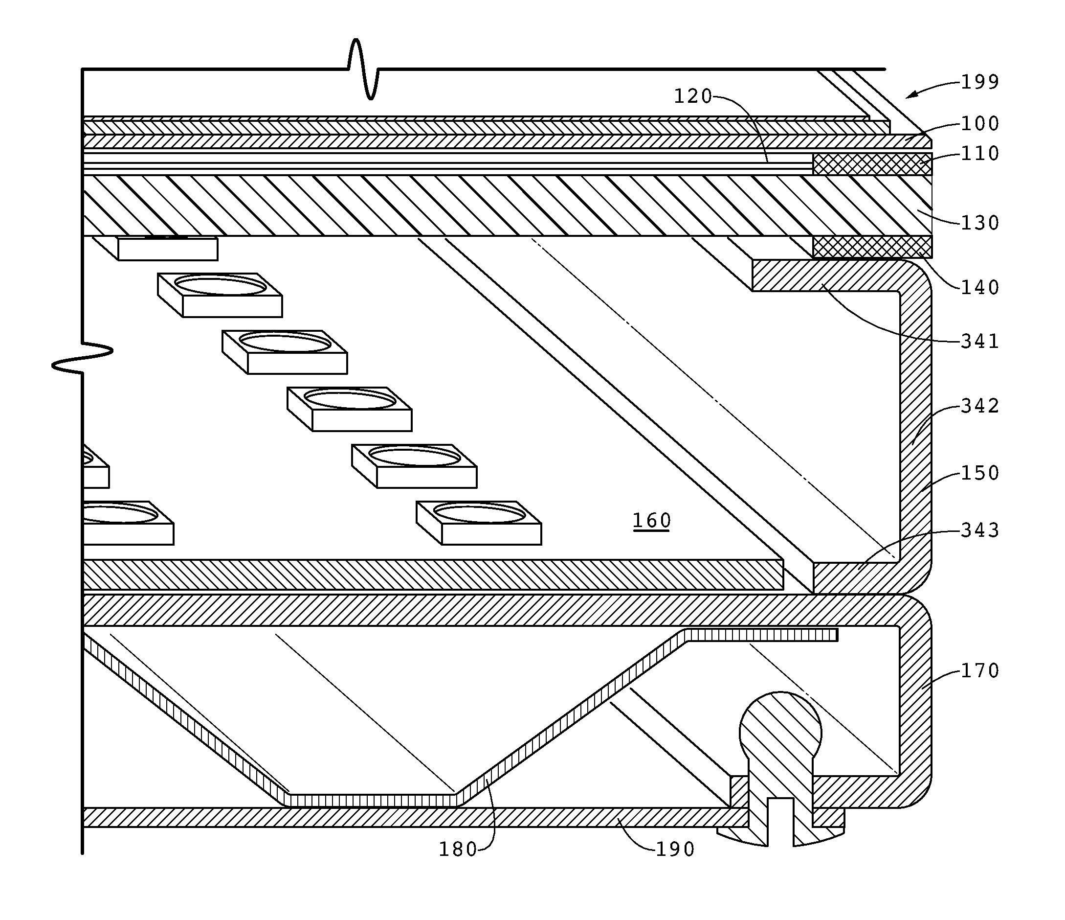
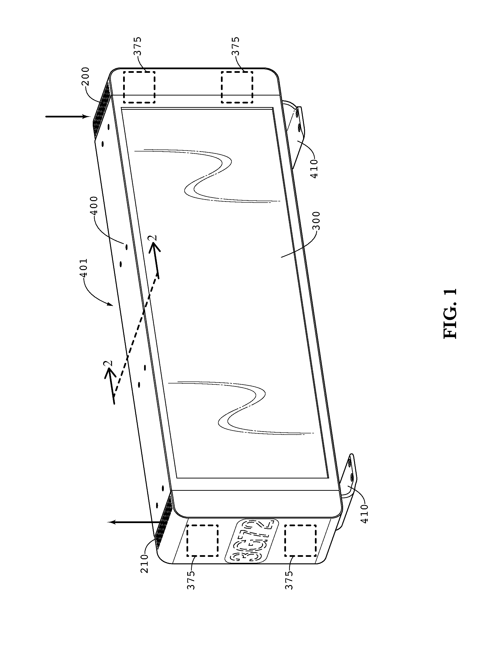
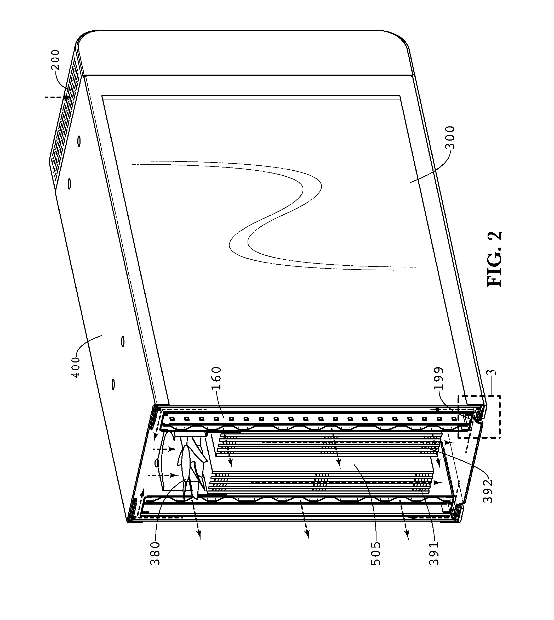
[0005]Exemplary embodiments disclosed herein provide a rigid LCD assembly including a LCD having a perimeter, a first layer of tape around the perimeter of the LCD, and a diffusing plate attached to the later of tape so as to create a cavity defined by the space between the LCD, tape, and diffusing plate. One or more optical films may be inserted into the cavity, and while constricted in directions perpendicular to the films, the films may be free to move slightly in the directions parallel to the films. A U-shaped backlight wall may attach to the diffusing plate and would contain a backlight. An optional thermal plate can be attached to the backlight wall, which can be used with a second thermal plate to define a channel for accepting cooling air.
[0006]The foregoing and other features and advantages of the exemplary embodiments of the present invention will be apparent from the following more detailed description of the particular embodiments, as illustrated in the accompanying dra...
PUM
 Abstract
Description
Claims
Application Information