Teardrop and offset notch bridging connector

a technology of notch bridging and notch notch, which is applied in the direction of rod connection, coupling, manufacturing tools, etc., can solve the problems of reducing the service life of the notch

Active Publication Date: 2014-09-18
SIMPSON STRONG TIE
View PDF2 Cites 11 Cited by
  • Summary
  • Abstract
  • Description
  • Claims
  • Application Information

AI Technical Summary

Benefits of technology

[0018]The exceptional strength of the interlocking connections between the bridging connector, the bridging member and the wall stud allow the bridging connector to be firmly connected with a single fastener that attaches the body of the bridging connector to the bridging member.

Problems solved by technology

Steel studs have excellent columnar strength when they are straight, but a significant portion of that strength is lost if the studs are twisted.
When metal studs twist or bend, they lose their weight-bearing capacity, multiplying the damage caused directly by fire.
The prior art brackets are all relatively labor intensive to install and their connections are all relatively weak.
The prior art also includes short bridging members that, like the wood blocking members mentioned above, span only adjacent studs and have ends tailored for fastening the wall studs, but these bridging members are relatively expensive because they use additional material to form the ends, they require a large number of fasteners, and they are necessarily of fixed length, which makes them useless if the spacing between any two studs has to be varied from the norm.
The prior art also includes elongated bridging members with a series of slots that are designed for mating with the opening in the wall stud webs, but these make relatively weak connections and also have the disadvantage that they cannot accommodate any variation in the spacing between studs.

Method used


Image

  • Teardrop and offset notch bridging connector
  • Teardrop and offset notch bridging connector
  • Teardrop and offset notch bridging connector

Examples


Embodiment Construction

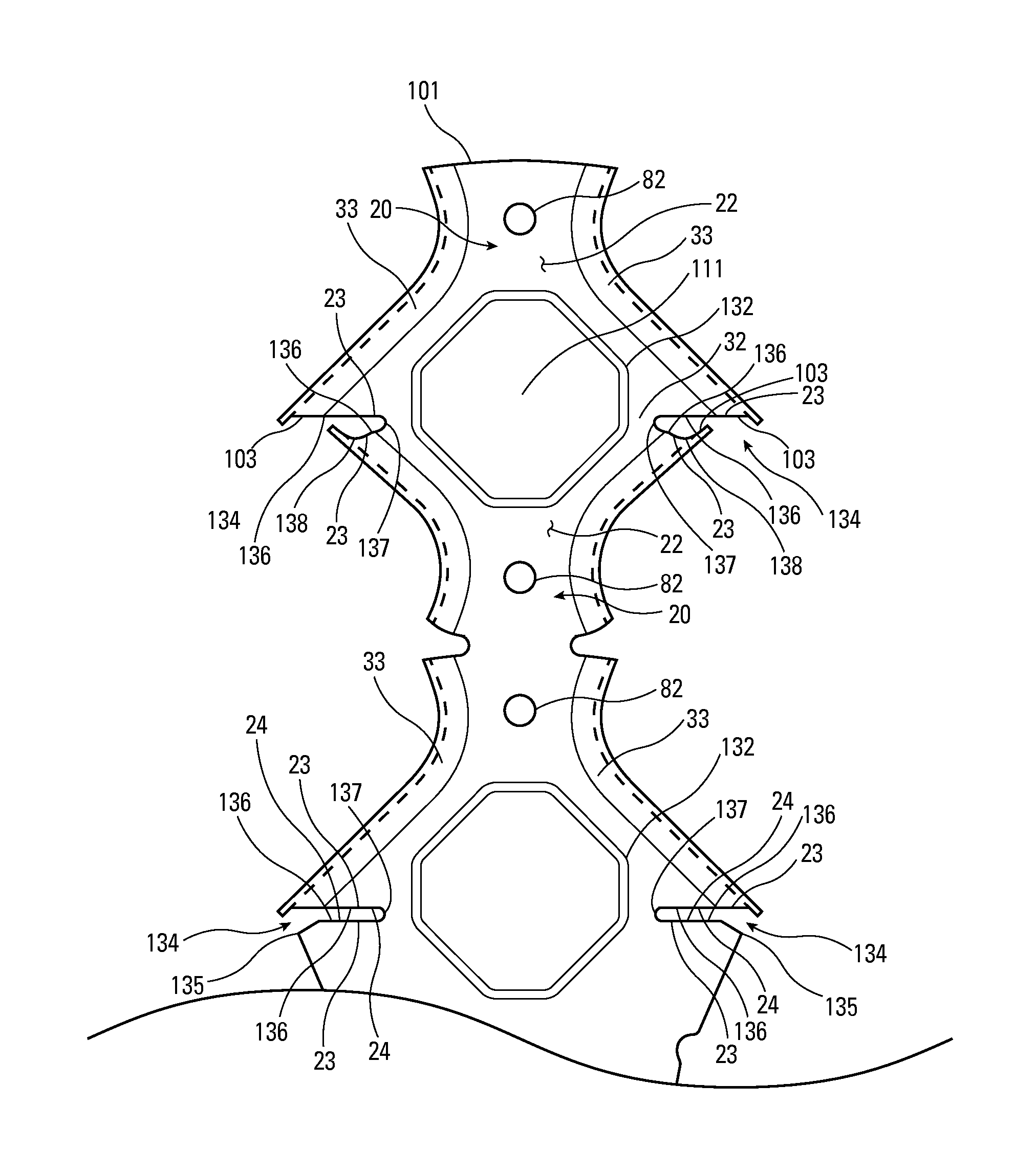
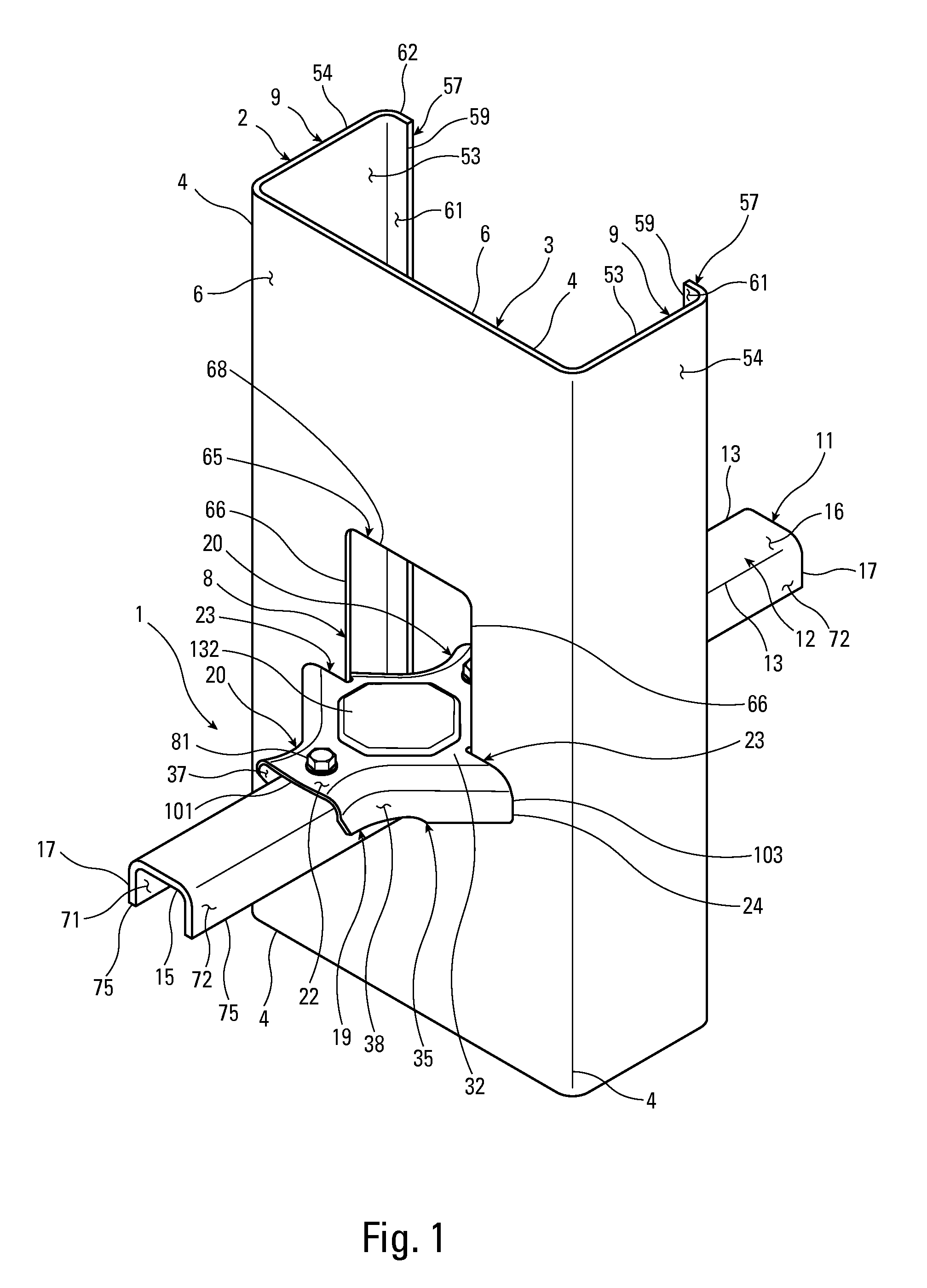
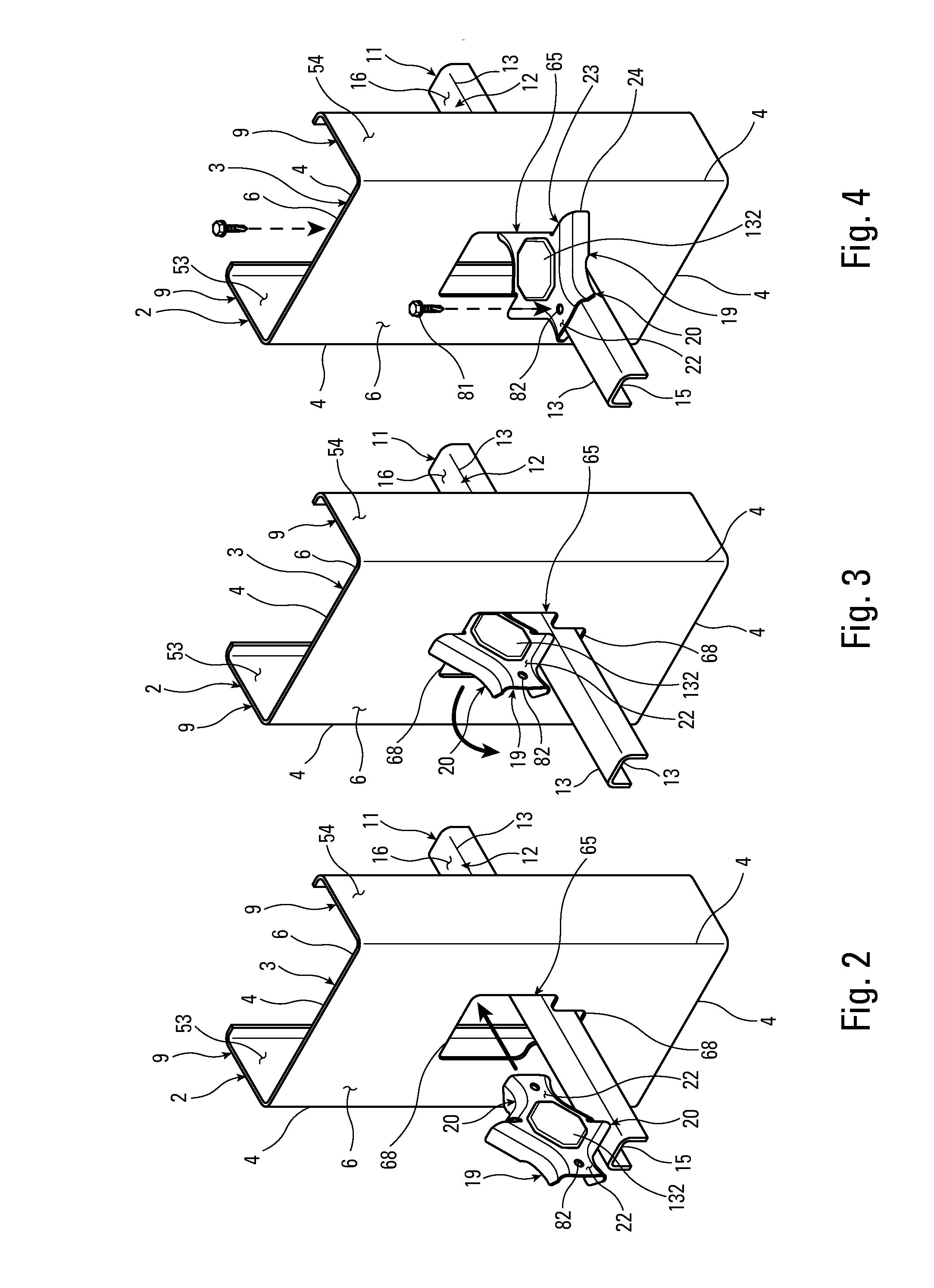
[0039]As shown in FIGS. 1, 5, 6, 16 and 17, the invention is a building connection 1 between a substantially vertical wall stud 2, a substantially horizontal bridging member 11, and a bridging connector 19. The wall stud 2 is typically one of several sequentially-arranged, cold-formed steel studs 2 in the frame of a building wall. The bridging member 11 is typically a separate cold-formed steel member that interfaces with and spans a plurality of wall studs 2. The bridging connector 19 is preferably made from cold-formed steel, but it could also be cast from a material such as aluminum or fabricated in another manner and from other suitable materials.

[0040]As shown in FIGS. 1-6, 19 and 20, the substantially vertical wall stud 2 preferably has a central web 3, a first side flange 9 integrally attached to the central web 3, and a second side flange 9 integrally attached to the central web 3. The central web 3 includes an opening 8. The most common shape for the opening 8 in an interio...


PUM

PropertyMeasurementUnit
heightaaaaaaaaaa
fireproofaaaaaaaaaa
columnar strengthaaaaaaaaaa

Abstract

A connection between metal studs and bridging members using a separate light gauge bridging connector with teardrop-shaped interface notches and longitudinally-offset interface notches that more effectively grip the web of the metal studs.

Description

BACKGROUND OF THE INVENTION[0001]The present invention relates to steel stud building wall systems and especially to apparatuses for stabilizing steed studs to prevent lateral movement and torsion in such systems.[0002]Many industrial, and a growing number of residential, buildings are constructed with steel stud wall framing for a variety of reasons. Steel framing is fireproof, does not warp, cannot be infested, and does not rot. When a wall is built with any kind of stud, wood or steel, it is generally desirable to fix sequential studs relative to each other and each against lateral movement and torsion. In wood-stud walls, a short piece of wood blocking is typically nailed to adjacent stud pairs to stabilize them. In steel-stud walls, an elongated steel bridging member is typically inserted horizontally through pre-punched openings in a series of vertical studs to keep them aligned. Steel studs have excellent columnar strength when they are straight, but a significant portion of ...

Claims


Application Information

Patent Timeline
Patent Type & Authority Applications(United States)
IPC IPC(8): E04B1/41B21D35/00
CPCE04B2/763B21D35/002F16B7/0493Y10T403/50
Inventor DAUDET, LARRY RANDALLOELLERICH, PAUL HOWARD
Owner SIMPSON STRONG TIE
Why Eureka
Try Eureka