
Pad conditioning process control using laser conditioning

a technology of laser conditioning and process control, applied in the direction of abrasive surface conditioning devices, lapping machines, manufacturing tools, etc., can solve the problems of uneven roughness across the polishing surface, less ability of the pad to properly and efficiently remove material from the substrate, and non-planar feature side of the substrate,

Inactive Publication Date: 2014-09-18
APPLIED MATERIALS INC
View PDF1 Cites 47 Cited by
  • Summary
  • Abstract
  • Description
  • Claims
  • Application Information

AI Technical Summary

Benefits of technology

The patent describes a method and apparatus for conditioning a polishing pad used in a polishing process. The method involves scanning the processing surface of the polishing pad with a laser beam that is reactive with the material of the pad, but not with the polishing medium. This laser beam is provided by an optical device and is used to condition the polishing pad to improve its performance during the polishing process. The technical effects of this method include improved polishing efficiency, reduced damage to the substrate, and improved quality of the polishing surface.

Problems solved by technology

As layers of materials are sequentially deposited and removed, the feature side of the substrate may become non-planar and require planarization and / or polishing.
The deformation includes smoothing of the polishing surface and / or unevenness in the plane of the polishing surface, as well as clogging or blockage of pores in the polishing surface that may lessen the ability of the pad to properly and efficiently remove material from the substrate.
However, while the rotation and / or downforce applied to the conditioning disk is controlled, the abrasive portion may not cut into the polishing surface evenly, which creates a difference in roughness across the polishing surface.
Additionally, as the cutting action is not readily controlled, the pad lifetime may be shortened.
Further, the cutting action of these conditioning devices and systems sometimes produce large asperities in the polishing surface.
While the asperities are beneficial in the polishing process, the asperities may break loose during polishing, which creates debris that may contribute to defects in the substrate.

Method used


Image

  • Pad conditioning process control using laser conditioning
  • Pad conditioning process control using laser conditioning
  • Pad conditioning process control using laser conditioning

Examples


Embodiment Construction

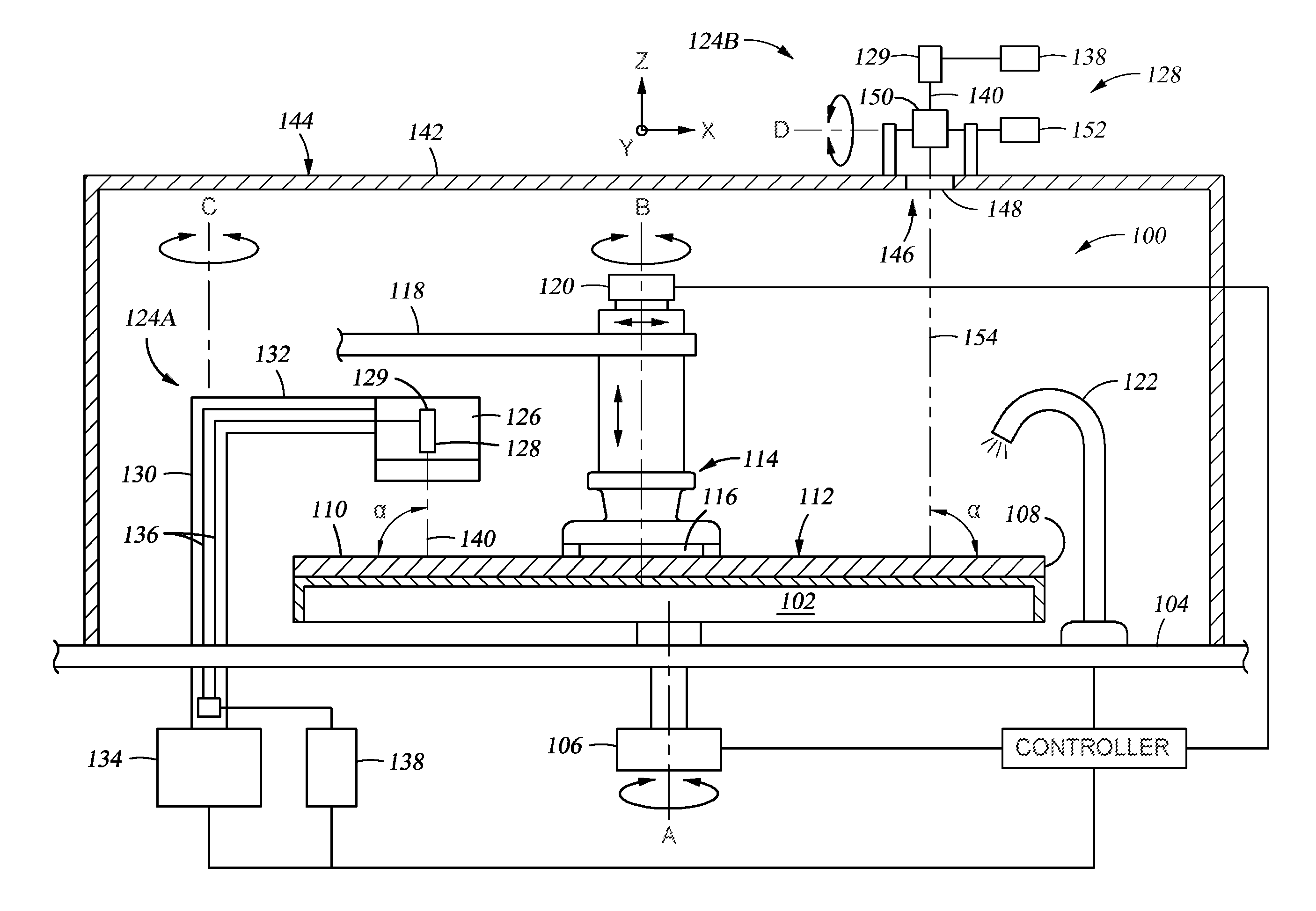
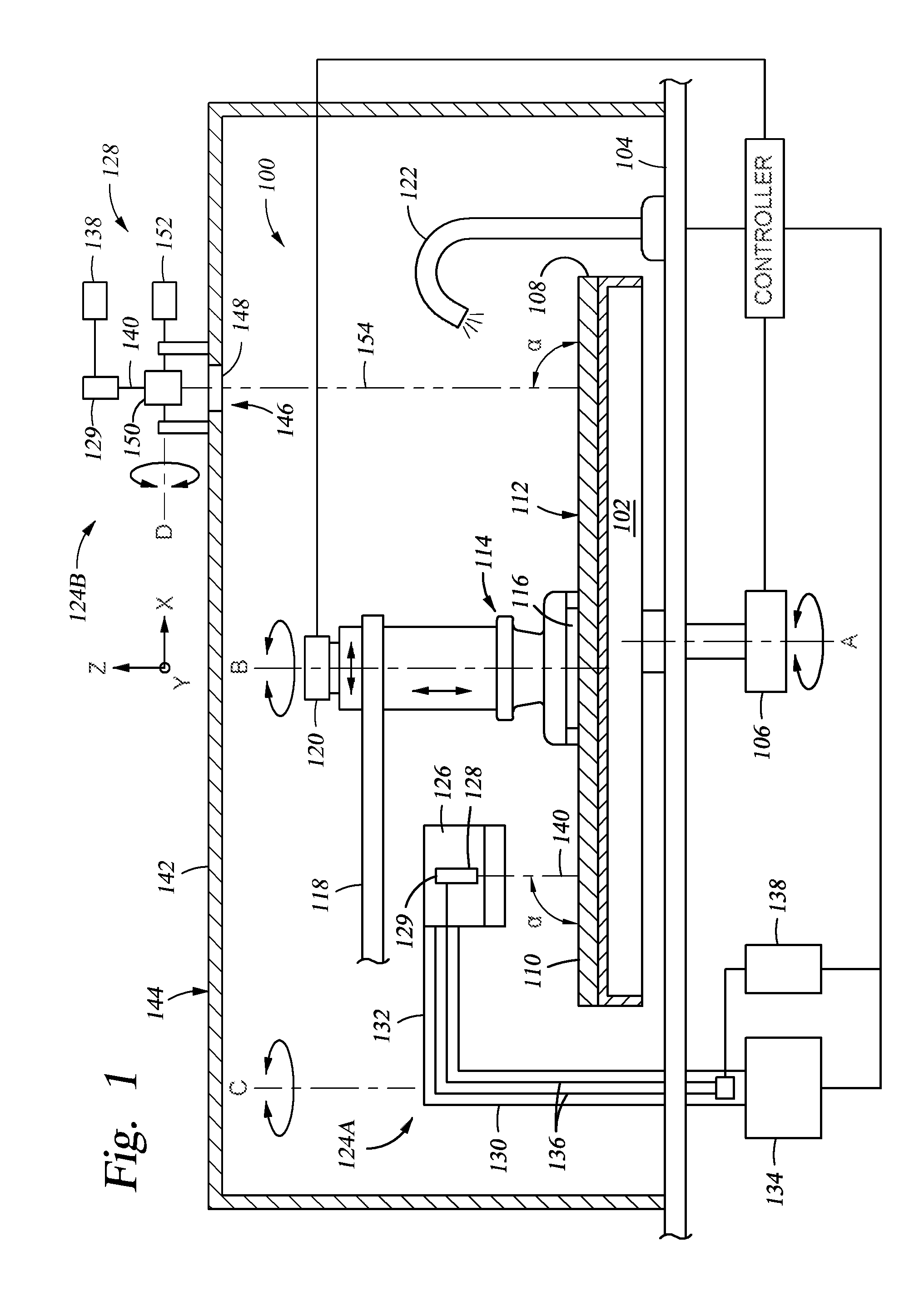
[0024]FIG. 1 is a partial sectional view of one embodiment of a processing station 100 that is configured to perform a polishing process, such as a chemical mechanical polishing (CMP) process or an electrochemical mechanical polishing (ECMP) process. The processing station 100 may be a stand-alone unit or part of a larger processing system. Examples of a larger processing system that the processing station 100 may be utilized with include REFLEXION®, REFLEXION® GT, REFLEXION® LK, REFLEXION® LK ECMP™, MIRRA MESA® polishing systems available from Applied Materials, Inc., located in Santa Clara, Calif., although other polishing systems may be utilized, including those from other manufacturers. Other polishing modules, including those that use other types of processing pads, belts, indexable web-type pads, or a combination thereof, and those that move a substrate relative to a polishing surface in a rotational, linear or other planar motion may also be adapted to benefit from embodiment...


PUM

PropertyMeasurementUnit
Lengthaaaaaaaaaa
Angleaaaaaaaaaa
Poweraaaaaaaaaa

Abstract

A method and apparatus for conditioning a polishing pad used in a substrate polishing process. In one embodiment, a method for conditioning a polishing pad utilized to polish a substrate is provided. The method includes providing relative motion between an optical device and a polishing pad having a polishing medium disposed thereon, and scanning a processing surface of the polishing pad with a laser beam to condition the processing surface, wherein the laser beam has a wavelength that is substantially transparent to the polishing medium, but is reactive with the material of the polishing pad.

Description

CROSS-REFERENCE TO RELATED APPLICATIONS[0001]This application claims benefit of U.S. Patent Application Ser. No. 61 / 780,155 (Attorney Docket No. 020572USAL) filed Mar. 13, 2013, and U.S. Patent Application Ser. No. 61 / 935,747 (Attorney Docket No. 021012USAL) filed Feb. 4, 2014. Both of the aforementioned patent applications are hereby incorporated by reference herein.BACKGROUND[0002]1. Field[0003]Embodiments of the present invention generally relate to control methods and apparatus for conditioning a substrate polishing pad using optical conditioning devices, such as laser conditioning devices.[0004]2. Description of the Related Art[0005]In the fabrication of integrated circuits and other electronic devices on substrates, multiple layers of conductive, semiconductive, and dielectric materials are deposited on or removed from a feature side, i.e., a deposit receiving surface, of a substrate. As layers of materials are sequentially deposited and removed, the feature side of the substr...

Claims


Application Information

Patent Timeline
IPC IPC(8): B24B53/017B24B37/04
CPCB24B37/042B24B53/017B24B49/18
Inventor BAJAJ, RAJEEVPENG, RIXINCORNEJO, MARIOBREZOCZKY, THOMASREDEKER, FREDOSTERHELD, THOMAS H.
Owner APPLIED MATERIALS INC
Features
  • Generate Ideas
  • Intellectual Property
  • Life Sciences
  • Materials
  • Tech Scout
  • Unparalleled Data Quality
  • Higher Quality Content
  • 60% Fewer Hallucinations
Learn More