
Medical monitoring system based on sound analysis in a medical environment

a medical environment and monitoring system technology, applied in the field of medical monitoring system based on sound analysis, can solve the problems of difficult to find improvement and mitigation measures, affecting patients negatively, and monitoring may be often too ambiguous, so as to mitigate, alleviate or eliminate one

Active Publication Date: 2014-09-18
KONINKLIJKE PHILIPS ELECTRONICS NV
View PDF7 Cites 31 Cited by
  • Summary
  • Abstract
  • Description
  • Claims
  • Application Information

AI Technical Summary

Benefits of technology

The present invention provides a method for monitoring a patient's sleep and sound analysis to identify potential sources of negative influence on the patient's rest and sleep. The method takes into account the patient's sleep cycle and the sound levels during specific periods of rest and sleep. By using advanced sound analysis techniques, the method can classify different sound sources and predict the actual impact of noise on the patient's rest and sleep. This information can be used to improve patient health and recovery.

Problems solved by technology

Recent research studies also indicate that patients are negatively impacted by the high noise levels.
There exist noise-level monitoring systems that measure the sound level in building spaces and provide real-time monitoring but these monitoring systems are typically not very specific about the source of the noise, rendering improvements and mitigation measures difficult to find.
However, the overall sound level is typically the only parameter on which such systems are designed to operate, and consequently the monitoring may often be too ambiguous, providing little information on what the actual noise sources are.
Additionally, the caretakers of patients, e.g. nurses, may not obtain valuable information about the sleep / rest quality of the patients that could be jeopardized by undesirable sounds i.e. noise.

Method used


Image

  • Medical monitoring system based on sound analysis in a medical environment
  • Medical monitoring system based on sound analysis in a medical environment
  • Medical monitoring system based on sound analysis in a medical environment

Examples


Embodiment Construction

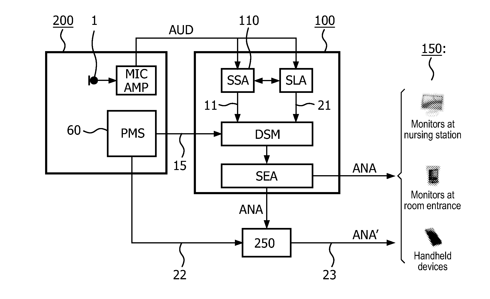
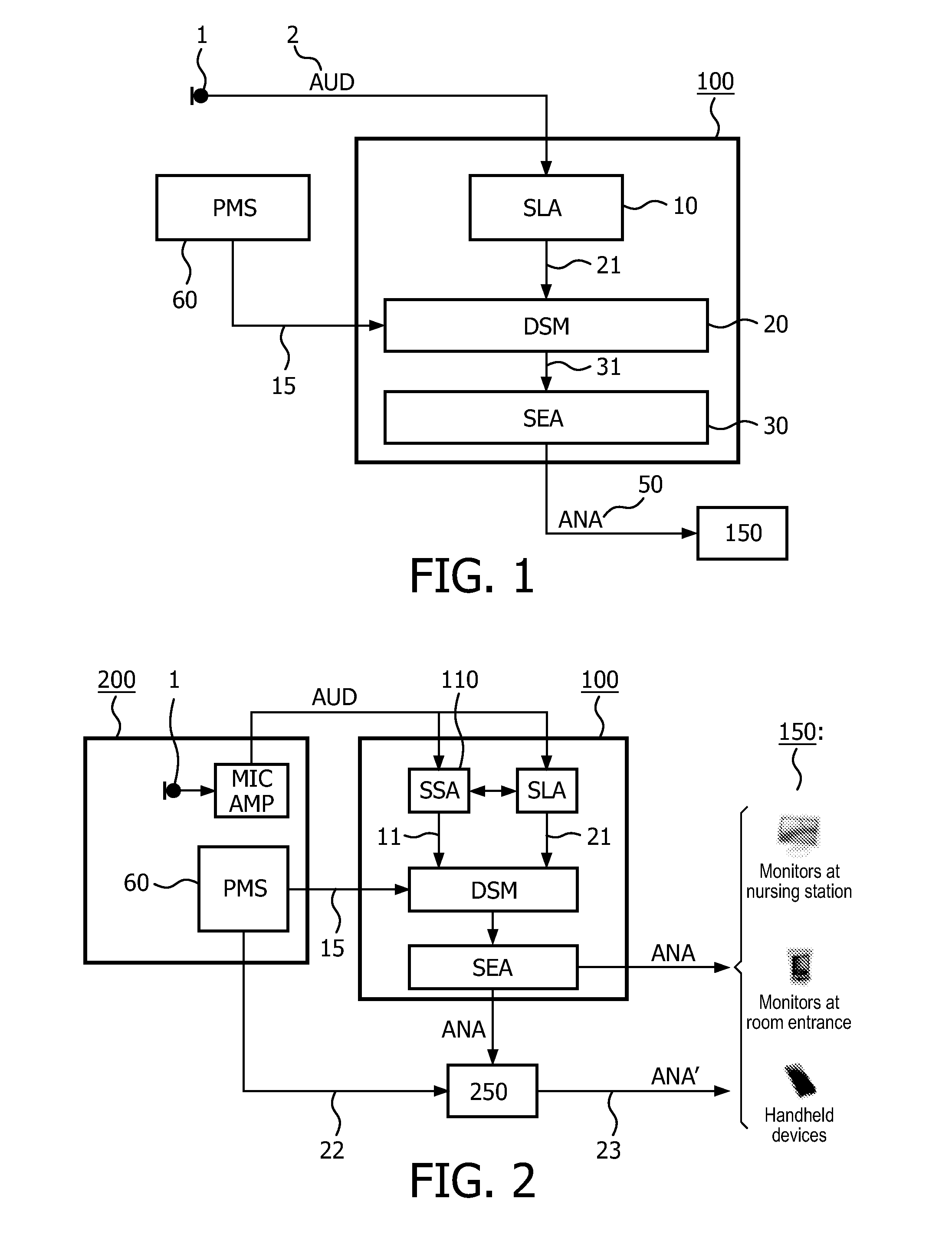
[0043]FIG. 1 shows a schematic drawing of a monitoring system 100 according to the present invention.

[0044]The system comprises a sound level analyzer SLA 10, the sound-level analyzer being arranged for receiving an audio signal AUD 2 indicative of sound near a patient (not shown), the sound-level analyzer being capable of providing an indicator for perceived levels of sound from a number of sound events, e.g. wherein the sound level analyzer have an appropriate perceptual model for providing perceived loudness. It should be noted that the SLA may provide a plurality of indicators for perceived loudness, e.g. for various time windows, and / or different frequency bands. Notice that the SLA does typically not know beforehand what the actual number of sound events is.

[0045]Additionally, the system 100 has a data storage modality DSM 20, the data storage modality being arranged for receiving and storing said indicator for perceived levels of sound from the number of sound events from the...


PUM


Abstract

The invention relates to a medical monitoring system (100) based on sound analysis in a medical environment. A sound level analyzer (SLA, 10) is capable of providing an indicator for perceived levels of sound from a number of sound events, and a data storage modality (DSM, 20) is receiving and storing said indicator for perceived levels of sound and also corresponding information from an associated patient monitoring system (PMS, 60) handling information indicative of a physical and / or mental condition of a patient under influence by sound. A sound event analyzer (SEA, 30) is further being arranged for performing, within a defined time window, an overall sound analysis (ANA, 50) related to physical and / or mental condition of the patient that may be influenced by sound in order to assist or supervise medical personal with respect to the acoustic environment.

Description

FIELD OF THE INVENTION[0001]The present invention relates to a medical monitoring system based on sound analysis in a medical environment. The present invention also relates to a corresponding method for providing monitoring based on sound analysis in a medical environment, and a corresponding computer program product for implementing the invention.BACKGROUND OF THE INVENTION[0002]Noise levels in hospital setting may be surprisingly high, especially in intensive care units (ICU). Recent research studies also indicate that patients are negatively impacted by the high noise levels. Major noise sources in ICU environments may be attributed to the behavior of staff, including speech and other activities.[0003]MacKenzie et al. (“Noise levels and noise sources in acute care hospital wards,” Building Serv. Eng. Res. Technol. 28, 2 (2007) pp. 117-131) have for example observed and classified noise sources in three 24-hour sessions in ICUs, and have identified a considerable number of avoida...

Claims


Application Information

Patent Timeline
IPC IPC(8): G06F19/00A61B5/0205A61B5/00A61B5/0402A61B5/0496A61B5/0488A61B5/11A61B5/0476
CPCG06F19/34A61B5/1118A61B5/0205A61B5/0476A61B5/4815A61B5/0496A61B5/0488A61B5/0077A61B5/0402A61B5/0006A61B5/165A61B5/4884A61B2505/03A61B2560/0242G16H40/63A61B5/333A61B5/38A61B5/318A61B5/369A61B5/389A61B5/398
Inventor KOHLRAUSCH, ARMIN GERHARDFALCK, THOMASDEN BRINKER, ALBERTUS CORNELIS
Owner KONINKLIJKE PHILIPS ELECTRONICS NV
Learn More