Sweat collecting device

a technology for collecting devices and sweat, which is applied in the field of human sweat collection, can solve the problems of producing and collecting enough sweat for some testing, and achieve the effect of reducing the number of peopl

Active Publication Date: 2014-09-18
ELITECHGRP
View PDF12 Cites 28 Cited by
  • Summary
  • Abstract
  • Description
  • Claims
  • Application Information

AI Technical Summary

Benefits of technology

[0009]In further improving the prior art device, the free open end of the sweat collector tubing may be flared to more easily receive a small syringe or blunt needle for use in removal of sweat from the sweat collector tubing. Alternately, a guide passage may be provided in the sweat collector body to extend through the body from the chamber for receiving the flexible sweat collector tubing to outside the sweat collector body. The guide passage can have a tapered entrance from outside the body so can easily receive the end of a small syringe or blunt needle and the guide passage will guide the needle into the open end of the sweat collector tubing.

Problems solved by technology

While the prior art Macroduct® Sweat Collector described in the above referenced U.S. Pat. No. 4,542,751 works well in collecting sweat from infants for most testing currently being done, producing and collecting enough sweat for some testing is sometimes a problem.

Method used


Image

  • Sweat collecting device
  • Sweat collecting device
  • Sweat collecting device

Examples


Embodiment Construction

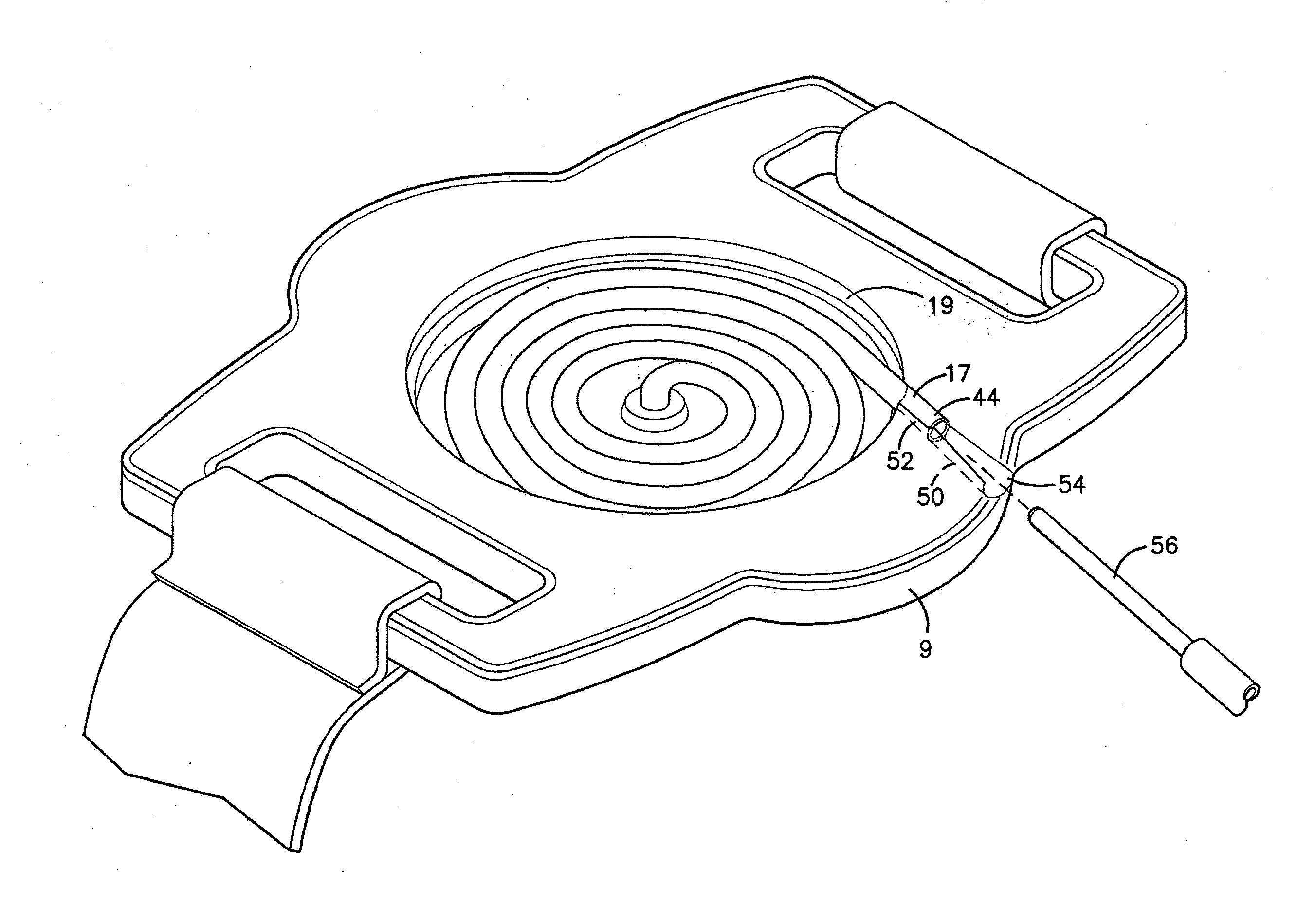
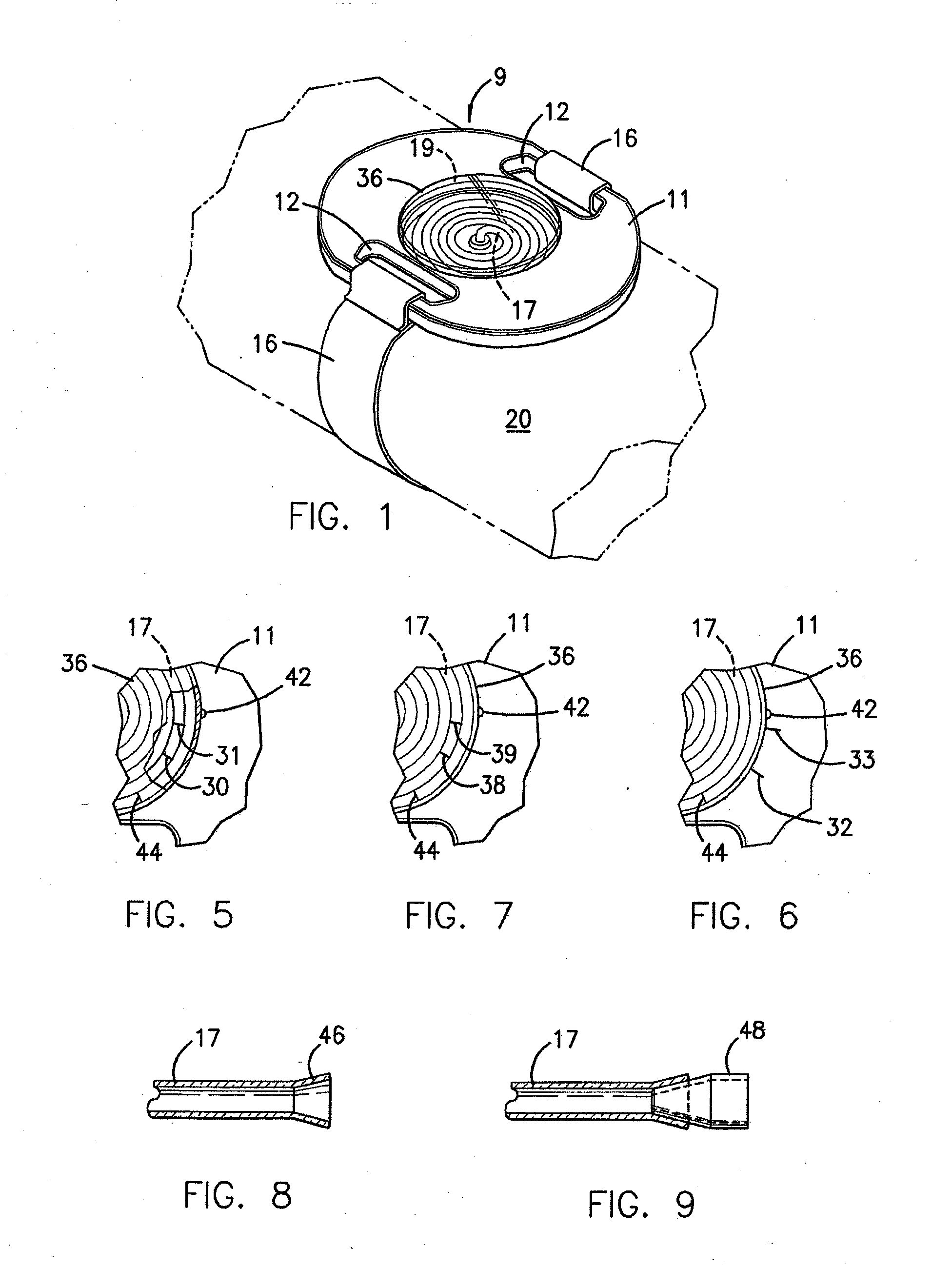
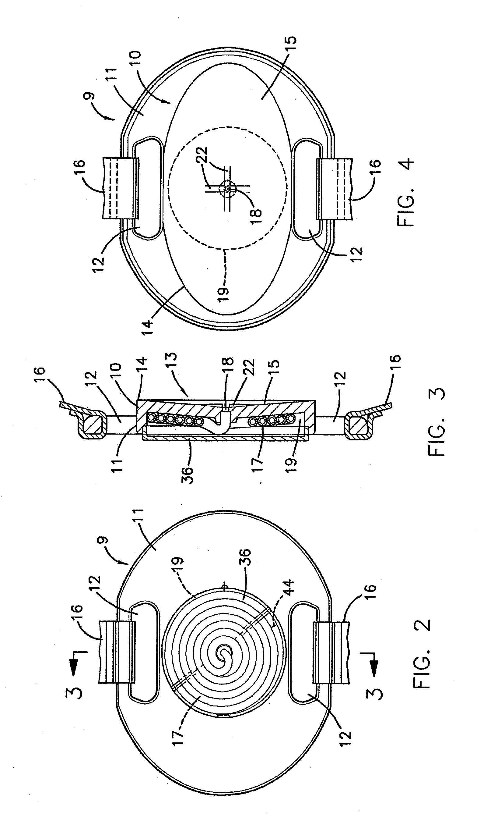
[0023]In the illustrated example embodiment as shown in FIGS. 1-4, similarly to the sweat collector shown in referenced prior art U.S. Pat. No. 4,542,751, the device of the invention comprises a sweat collector body 9 advantageously molded to shape from a suitable plastic material, such as polyethylene or polystyrene, and including a sweat collecting portion 10 projecting integrally from a back portion formed as a backing plate 11 provided with slot-like openings 12 at opposite sides thereof for the reception of straps 16 constituting means for attaching the device to a person. However, sweat collecting portion 10 projecting integrally from backing plate 11, rather than being of disc formation as in U.S. Pat. No. 4,542,751, is of elongate formation with the axis of elongation being substantially parallel to the slot-like openings 12.

[0024]The face of sweat collecting portion 10 has a shallow concavity 13 whose rim 14 lies wholly in a common plane and which is defined by a broad, swe...


PUM


Abstract

A sweat collection device includes an elongate concave sweat-collecting surface at a face thereof for placement over an iontophoresis-stimulated area of a patient's skin to collect sweat and pass it through an axial bore in the concavity. A length of flexible tubing is secured to the axial bore for receiving and storing the collected sweat. A chamber may be provided for holding the tubing in flat coiled condition. Collected sweat builds up within the tubing from the axial bore. The device can include markings to indicate when a minimum amount of sweat has been collected in the tubing and can indicated a range for collected sweat that takes into account variations in the tubing. An open end of the tubing can be flared for easy insertion of a blunt needle to extract sweat or a guide passage can guide insertion of the needle into the open end of the tubing.

Description

BACKGROUND[0001]1. Field of the Invention[0002]The present invention relates generally to the collection of human sweat for medical evaluation and is particularly directed to sweat collection devices.[0003]2. Related Art[0004]It is known that the concentrations of sodium and chloride are considerably above normal in the sweat of individuals suffering from cystic fibrosis. Sweat testing is routinely used to diagnose cystic fibrosis, particularly in infants, where such testing is often done between birth and about four weeks of age. In one method of sweat collection, as described in U.S. Pat. No. 4,542,751, incorporated herein by reference, sweating is induced in a substantially flat area of skin by pilocarpine iontophoresis, usually performed using an electrode with a substantially circular pilocarpine containing gel disc, as described in U.S. Pat. No. 4,383,529, incorporated herein by reference, and as manufactured by Wescor, Inc. of Logan, Utah, as a Pilogel® Iontophoresis Disc, pl...

Claims


Application Information

Patent Timeline
Patent Type & Authority Applications(United States)
IPC IPC(8): A61B10/00
CPCA61B10/0064A61B5/4266A61B5/443A61B5/6824A61B5/6831A61B2503/045
Inventor BRISCOE, DENNIS R.MC EUEN, BRYCE P.
Owner ELITECHGRP
Why Eureka
Try Eureka