
Micromachined mass flow sensor with condensation prevention and method of making the same

a mass flow sensor and micromachined technology, applied in the field of micromachined silicon sensors, can solve the problems of affecting the flow readout, clogging of additional liquid condensation, and not changing the basic performance of the so as to maximize the sensitivity of the said silicon mass flow sensor, save the energy necessary for operation, and accurately measure the

Active Publication Date: 2014-09-25
WISENSTECH
View PDF2 Cites 15 Cited by
  • Summary
  • Abstract
  • Description
  • Claims
  • Application Information

AI Technical Summary

Benefits of technology

This patent describes an improved design for a silicon mass flow sensor which uses less energy than previous versions. It includes two main components: a micro-heater (which generates the heat needed) and two thermometers (which measure the temperatures before and after the heat has been applied). One advantage of this new design is that its use requires no external electricity. Another key feature is that one of the thermometers measures the actual temperature of the fluid being tested, while the others are located far from the heat source. This ensures accurate readings and helps achieve a steady state condition for the heat output. Additionally, the patent discusses alternative designs using different materials and shapes for better efficiency and precision. Overall, these improvements make the silicon mass flow sensor more reliable and effective for measuring small amounts of fluids.

Problems solved by technology

The technical problem addressed in this patent is how to create a silicon flow sensor that works effectively in environments with vapors or high humidity levels, while keeping its small size and being operable at low powers. Additionally, the desire for a more flexible and adaptable silicon flow sensor that can measure flow rates accurately regardless of the characteristics of the fluid remains unchanged.

Method used


Image

  • Micromachined mass flow sensor with condensation prevention and method of making the same
  • Micromachined mass flow sensor with condensation prevention and method of making the same
  • Micromachined mass flow sensor with condensation prevention and method of making the same

Examples


Embodiment Construction

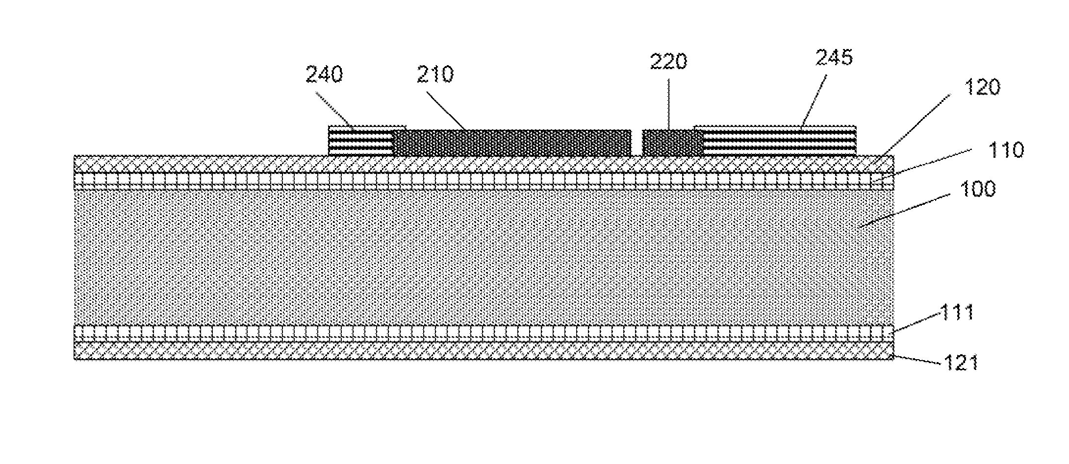
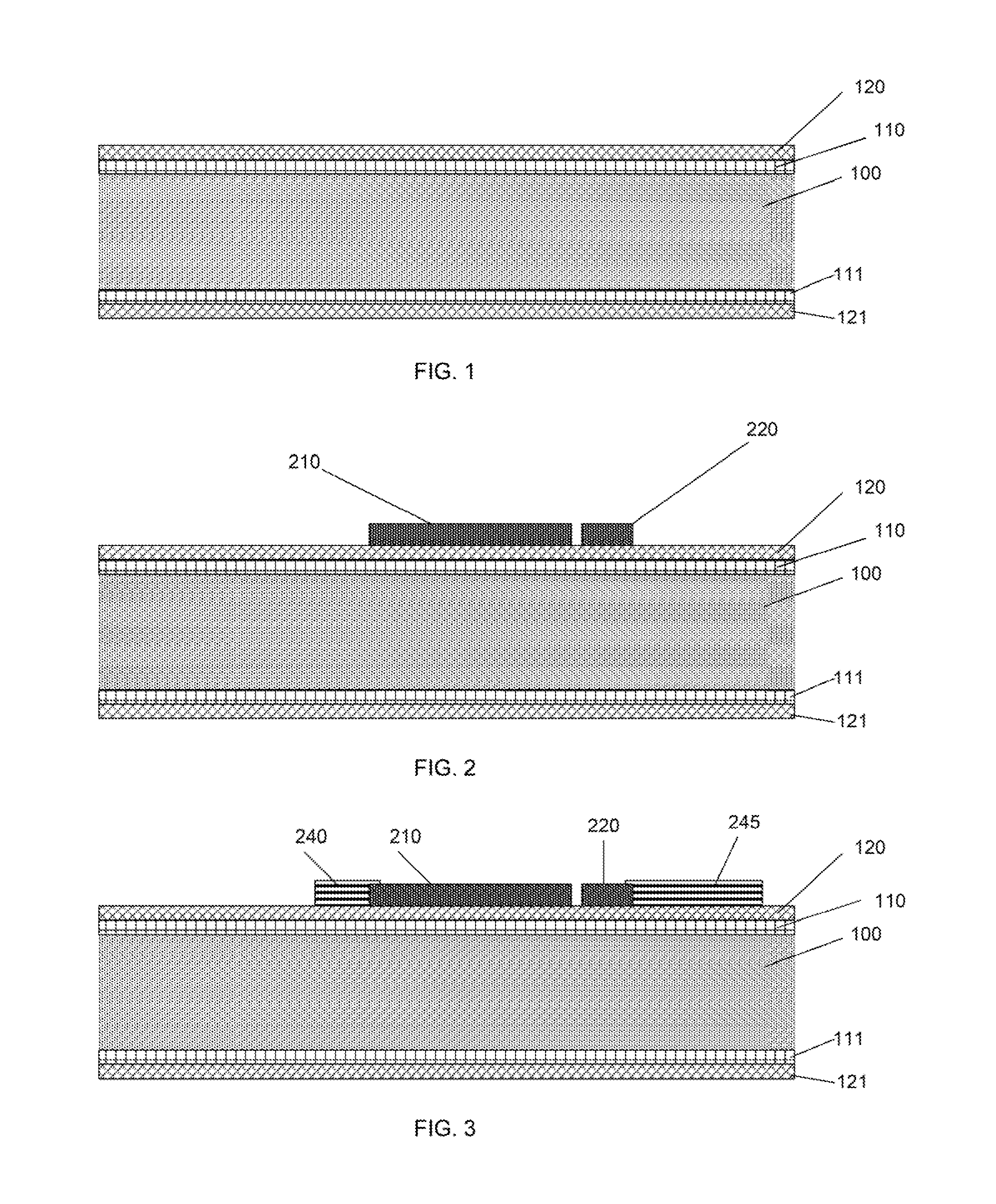
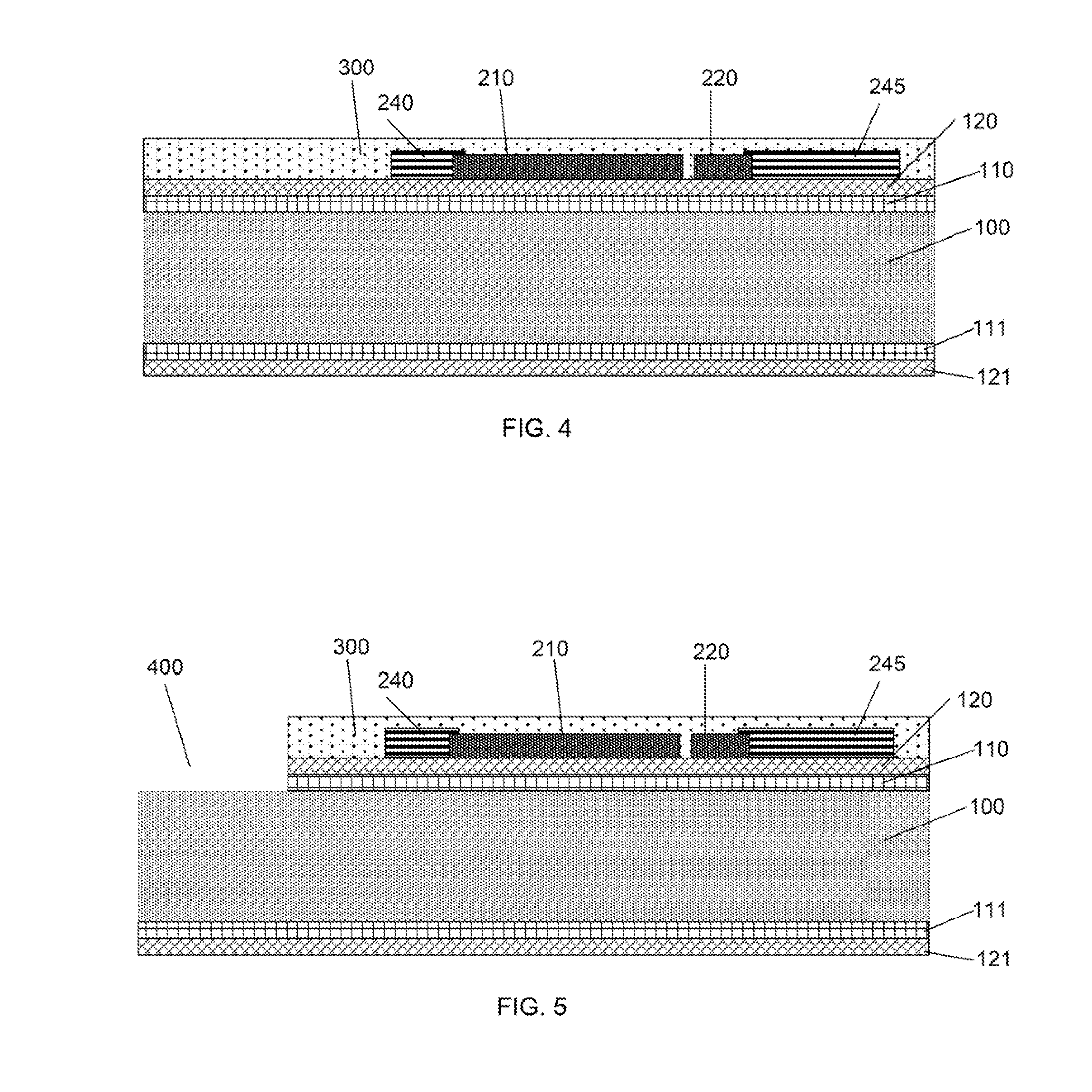
[0028]The preferred micromachining process for making of the said invention starts from the preparation of the isolation cavity process mask and process stop (110 and 111) on the single crystal silicon substrate (100) with a thickness from 0.35 to 0.50 mm. Then the process is formed by the membrane formation for supporting the sensing, elements and the said heat source (120) as shown in FIG. 1. The isolation cavity process mask and process stop (110 and 111) can be made of silicon oxide via thermal oxidization growth in an oven with a thickness of 100 to 300 nm but preferably 150 nm. The membrane material is usually selected to be polyimide or silicon nitride for its mechanical strength. The polyimide membrane is made via spin coating with a thickness of 2 to 8 micro meters. The silicon nitride is preferably made via the low pressure chemical vapor deposition (LPCVD) process with a thickness from 800 to 2000 nm but preferably of 1000 to 1200 rim for the management of the total membr...


PUM


Abstract

The design and manufacture method of a silicon mass flow sensor made with silicon Micromachining MEMS, Micro Electro Mechanical Systems) process for applications of gas flow measurement with highly humidified or liquid vapors is disclosed in the present invention. The said silicon mass flow sensor operates with an embedded heater and an adjacent control temperature sensor beneath the integrated calorimetric and thermal dissipative sensing thermistors. When the condensation takes place at the surface of the said silicon mass flow sensor, the embedded heater shall be turned on to elevate the temperature of the supporting membrane or substrate for the sensing thermistors. The elevated temperature shall be adjusted to above the vaporization temperature with the feedback data of the adjacent temperature sensor such that the surface condensation due to the presence of the liquid vapors in a gas flow can be effectively eliminated.

Description


Claims


Application Information

Patent Timeline
Owner WISENSTECH
Learn More