
Process for manufacturing potable water and apparatus therefor

a manufacturing process and technology for potable water, applied in the nature of treatment water, waste water treatment from quaries, membranes, etc., can solve the problems of environmental pollution, equipment and operation cost, and the method has a cost, so as to save energy necessary for distillation and improve the utilization efficiency of solar energy. , the effect of reducing the cost of equipment and operation

Inactive Publication Date: 2014-10-30
JFEENG CORP
View PDF0 Cites 42 Cited by
  • Summary
  • Abstract
  • Description
  • Claims
  • Application Information

AI Technical Summary

Benefits of technology

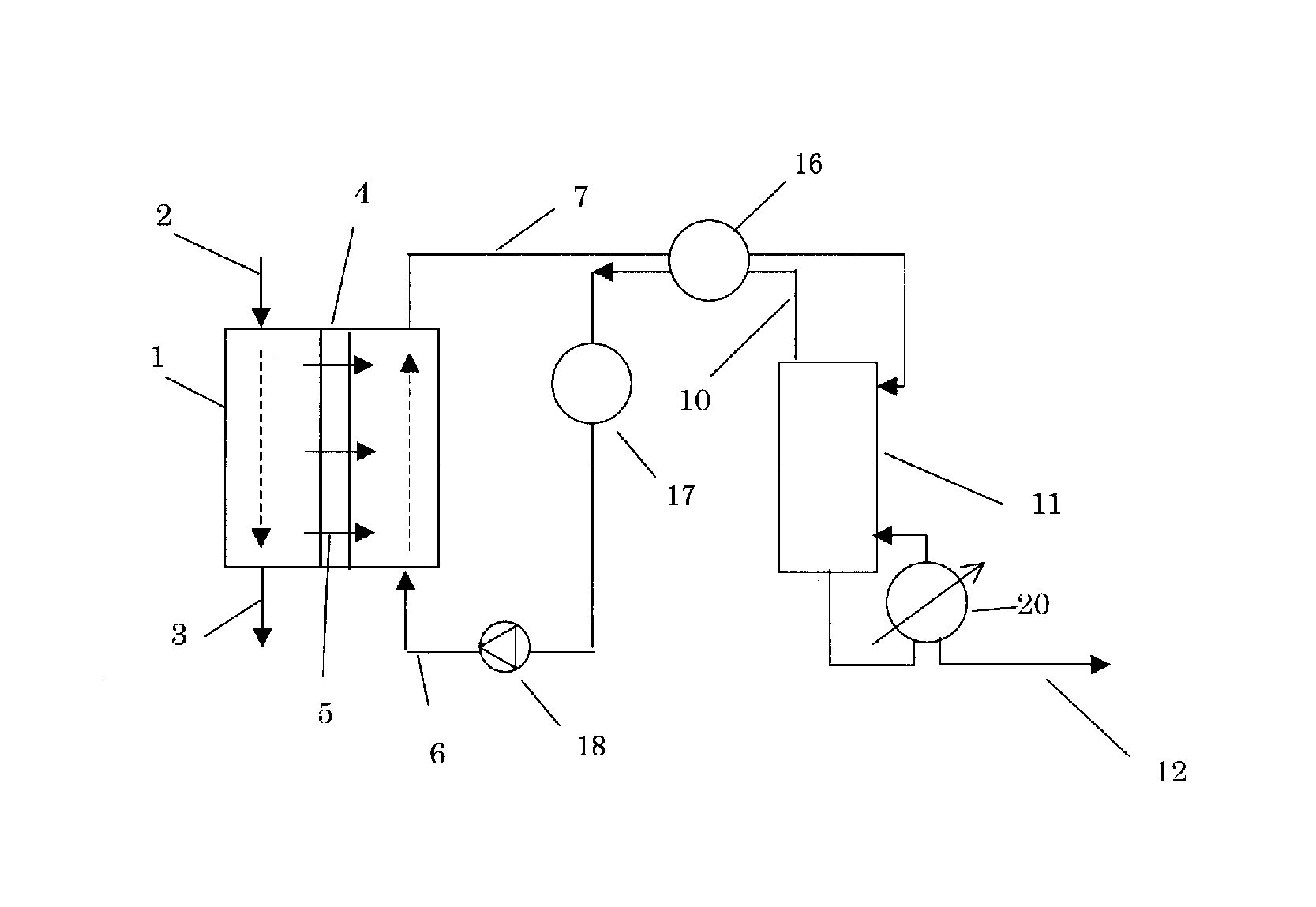
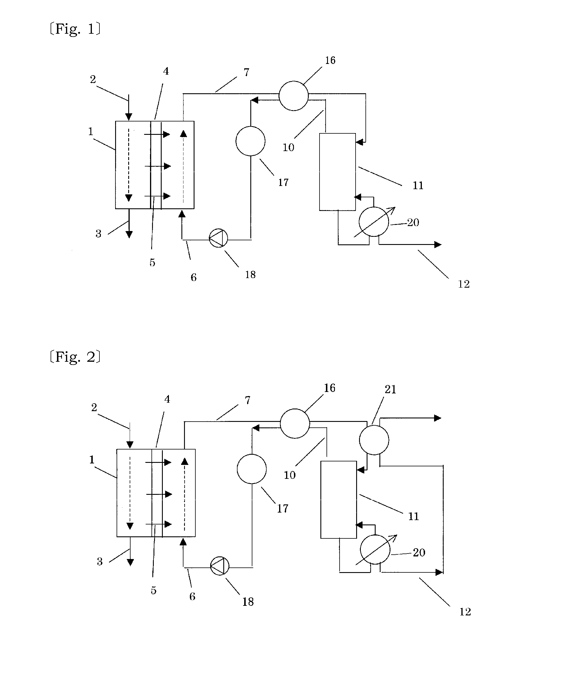
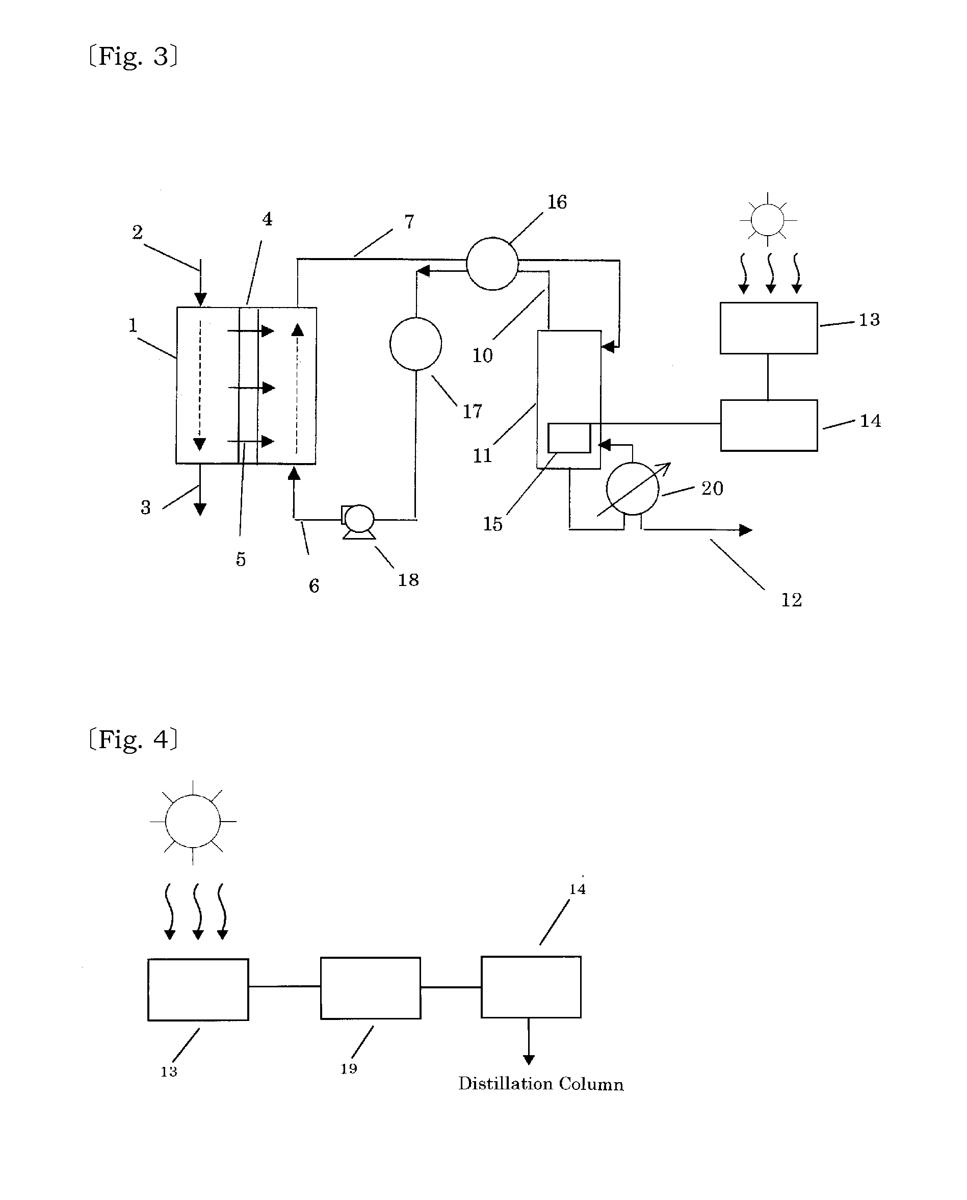
The invention is a method for recycling a solution used in a process of making potable water. This is done by cooling the gas containing carbon dioxide, ammonia, and water that is separated from the solution. This decreases the energy needed for the process and allows for more water to be taken out, making the structure more compact. The invention also uses solar energy as a heat source, which improves the efficiency of the process. Additionally, the concentration of the solution can be adjusted for efficient operation of the process. Overall, this method reduces manufacturing costs and allows for more water production with less energy.

Problems solved by technology

The methods have a problem requiring cost for equipments and operation due to the necessity for presuriging to a high pressure.
Since the separated accompanied water contains salt content, organic materials, suspensoids and the like, when it is discharged as is, a problem of environmental pollution occurs.

Method used


Image

  • Process for manufacturing potable water and apparatus therefor
  • Process for manufacturing potable water and apparatus therefor
  • Process for manufacturing potable water and apparatus therefor

Examples


example 1

[0141]The draw solution containing 8.5 mol / L ammonia and 5.6 mol / L carbon dioxide was used. All of the remainder was water, and a molar ratio of ammonia to carbon dioxide is 1.5.

[0142]The inflow rate at the inlet port of the draw solution of the semi-permeable membrane apparatus was set 200 kg / hr. An aqueous sodium chloride solution which simulated seawater was used as the liquid to be treated. The volume of water which passed the separation apparatus which simulated the semi-permeable membrane to migrate into the draw solution was 1,000 kg / hr., and the volume of the dilute draw solution discharged from the outlet port of the draw solution was 1,200 kg / hr., and its temperature was 28° C.

[0143]The dilute draw solution was heated to 38° C. by the heat exchange with the gas discharged from the top of the distillation column, and delivered into the first stage at the upper portion of the distillation column.

[0144]The distillation column was a tray tower type with 30 stages, and a reboil...

example 2

[0148]The draw solution containing 6.9 mol / L ammonia and 3.1 mol / L carbon dioxide was used. All of the remainder was water, and a molar ratio of ammonia to carbon dioxide is 2.2. The inside pressure of the distillation column was 59 kPa A.

[0149]The inflow rate at the inlet port of the draw solution of the separation apparatus which simulated the semi-permeable membrane apparatus was set 0.42 kg / hr. An aqueous sodium chloride solution which simulated seawater was used as the liquid to be treated. The volume of water which passed the separation apparatus which simulated the semi-permeable membrane to migrate into the draw solution was 2.52 kg / hr., and the volume of the dilute draw solution discharged from the outlet port of the draw solution was 2.94 kg / hr., and its temperature was 29° C.

[0150]The dilute draw solution was heated to 59° C. by the heat exchange with the gas discharged from the top of the distillation column, and delivered into the first stage at the upper portion of the...

example 3

[0153]The draw solution containing 6.8 mol / L ammonia and 4.0 mol / L carbon dioxide was used. All of the remainder was water, and a molar ratio of ammonia to carbon dioxide is 1.7. The inside pressure of the distillation column was atmospheric pressure.

[0154]The inflow rate at the inlet port of the draw solution of the separation apparatus which simulated the semi-permeable membrane apparatus was set 250 kg / hr. An aqueous sodium chloride solution which simulated seawater was used as the liquid to be treated. The volume of water which passed the separation apparatus which simulated the semi-permeable membrane to migrate into the draw solution was 1,000 kg / hr., and the volume of the dilute draw solution discharged from the outlet port of the draw solution was 1.25 kg / hr., and its temperature was 40° C.

[0155]The dilute draw solution was heated to 92° C. by the heat exchange with the gas discharged from the top of the distillation column, and delivered into the first stage at the upper po...


PUM

PropertyMeasurementUnit
pressureaaaaaaaaaa
temperatureaaaaaaaaaa
concentrationaaaaaaaaaa

Abstract

It is to provide a process for manufacturing potable water from a liquid to be treated, such as seawater by using forward osmosis membrane, wherein the solution after the separation of water from dilute draw solution diluted by the migration of water from the liquid to be treated, is stably regenerated and reutilized and an apparatus therefor, and the process and apparatus are a process for manufacturing potable water which comprises, a forward osmosis step wherein a liquid of which solvent is water is allowed to contact with a draw solution produced by dissolving a prescribed amount of a volatile material in water through a semi-permeable membrane, and water in said liquid is allowed to migrate to said draw solution through said semi-permeable membrane, a distillation step wherein a dilute draw solution having been diluted with water which was produced in said step is adjusted to a prescribed temperature, and then is delivered to a distillation column where gas comprising the volatile material and water vapor is discharged from the top of the column and potable water is discharged from the bottom of the column, and a cooling • regeneration step wherein said draw solution is regenerated by cooling said gas and an apparatus therefor.

Description

TECHNICAL FIELD[0001]This invention relates to a process for manufacturing potable water by purifying, such as seawater or brackish water using semi-permeable membrane and an apparatus therefor.BACKGROUND ART[0002]Although various methods are known for purifying seawater using semi-permeable membrane, most of the methods which have been developed are reverse osmosis where a pressure higher than the osmotic pressure is applied to seawater to force permeation of water. The methods have a problem requiring cost for equipments and operation due to the necessity for presuriging to a high pressure. Whereas, when a salt solution having a concentration higher than seawater is being present through semi-permeable membrane, water can migrate to the salt solution by the osmotic pressure without pressuriging. When a solution containing volatile gas dissolved therein is used as the salt solution, the volatile gas can be evaporated to be separated by distilling the salt solution to obtain potable...

Claims


Application Information

Patent Timeline
Patent Type & Authority Applications(United States)
IPC IPC(8): B01D65/02B01D63/02C02F1/44B01D61/00
CPCB01D65/02C02F1/445B01D63/02B01D61/002C02F1/04C02F1/048C02F1/14C02F1/16C02F1/444C02F2001/5218C02F2103/08C02F2103/10C02F2103/365C02F2209/02C02F2303/10C02F2303/16B01D2311/2669Y02W10/30Y02W10/37B01D63/043B01D2313/08Y02A20/131Y02A20/124B01D61/0022
Inventor FUCHIGAMI, KOJIMIZUKAMI, TAKESHIKUNUGI, MAKOTOUETAKE, NORIHITOUCHIYAMA, TAKESHITOMIDA, YOHEI
Owner JFEENG CORP
Learn More