
Membrane contactor for dehumidification systems

a membrane contactor and dehumidification technology, applied in the field of contactors, can solve the problems of limiting the efficiency of the contactor, and many problems with the conventional contactor

Active Publication Date: 2014-09-25
CARRIER CORP
View PDF12 Cites 5 Cited by
  • Summary
  • Abstract
  • Description
  • Claims
  • Application Information

AI Technical Summary

Benefits of technology

The invention provides a contactor for a dehumidification system that has several contact modules. Each module has a membrane through which a hygroscopic material flows. The membrane of one module is different from the others in its ability to hold water. This design has technical benefits in improving the function and efficiency of the dehumidification system.

Problems solved by technology

Because the membrane is hydrophobic, the membrane will not allow liquid water to pass through the pores into the gas side of the membrane.
Several problems exist with conventional contactors.
In addition, the heat and mass transfer between the liquid and the gas within the contactor occur at different rates, thereby limiting the efficiency of the contactor.

Method used


Image

  • Membrane contactor for dehumidification systems
  • Membrane contactor for dehumidification systems
  • Membrane contactor for dehumidification systems

Examples


Embodiment Construction

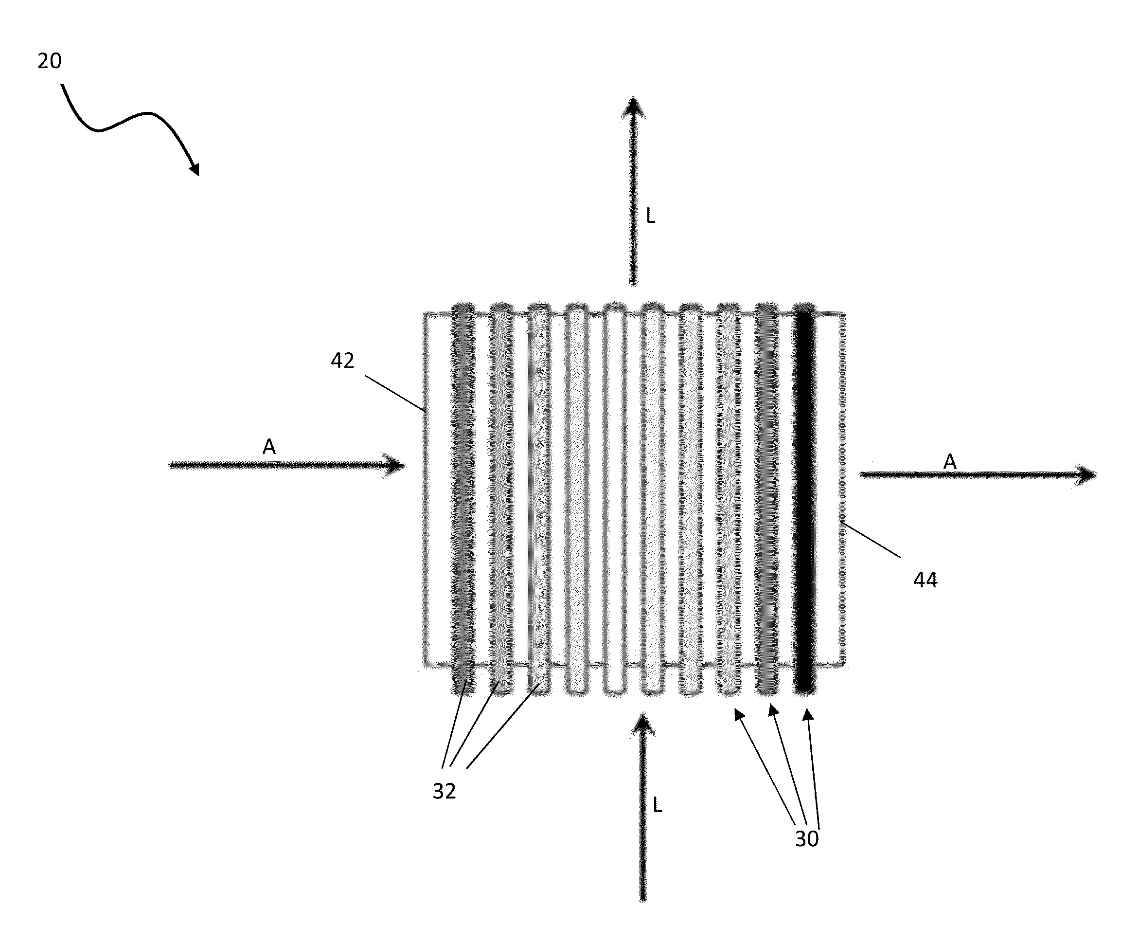
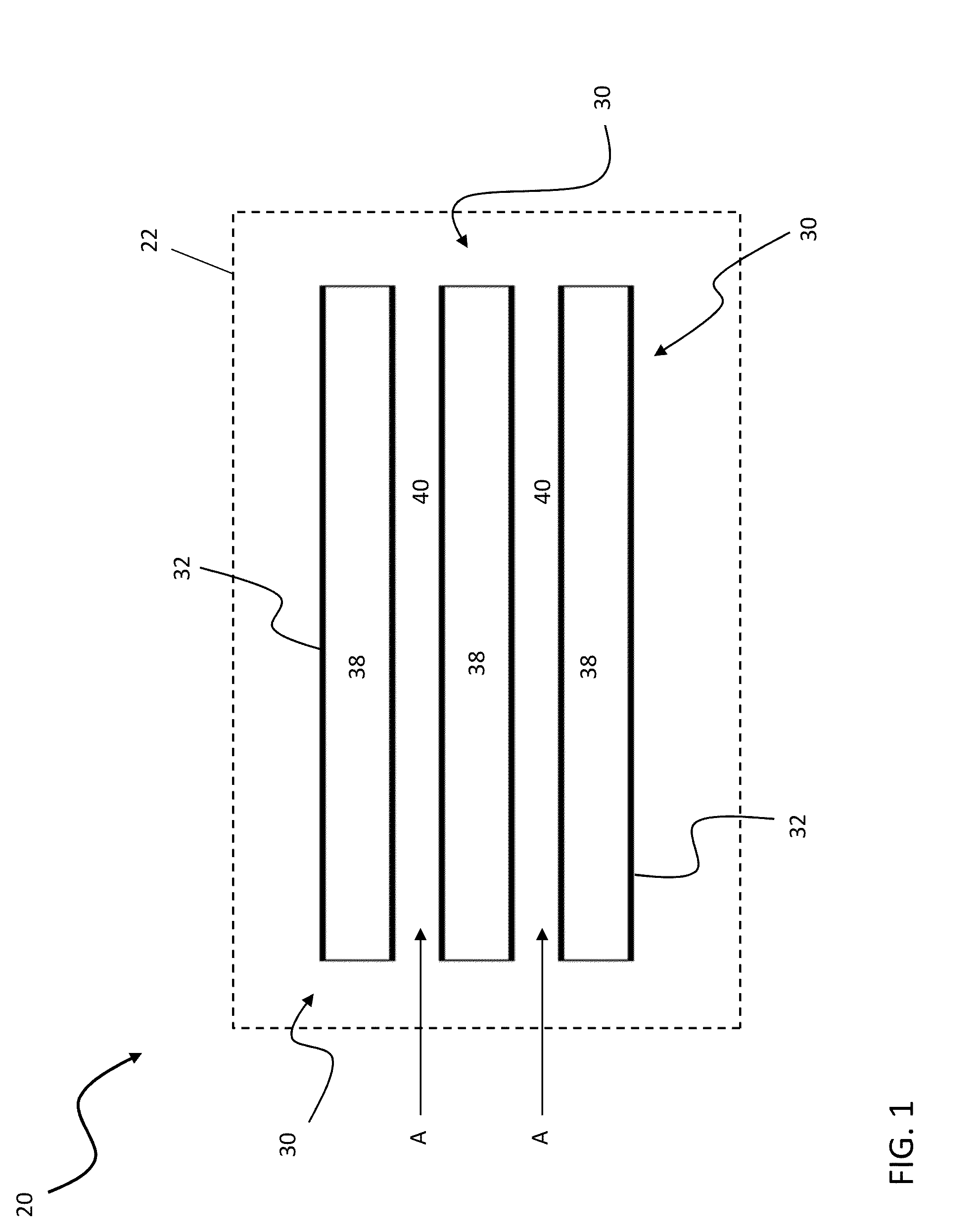
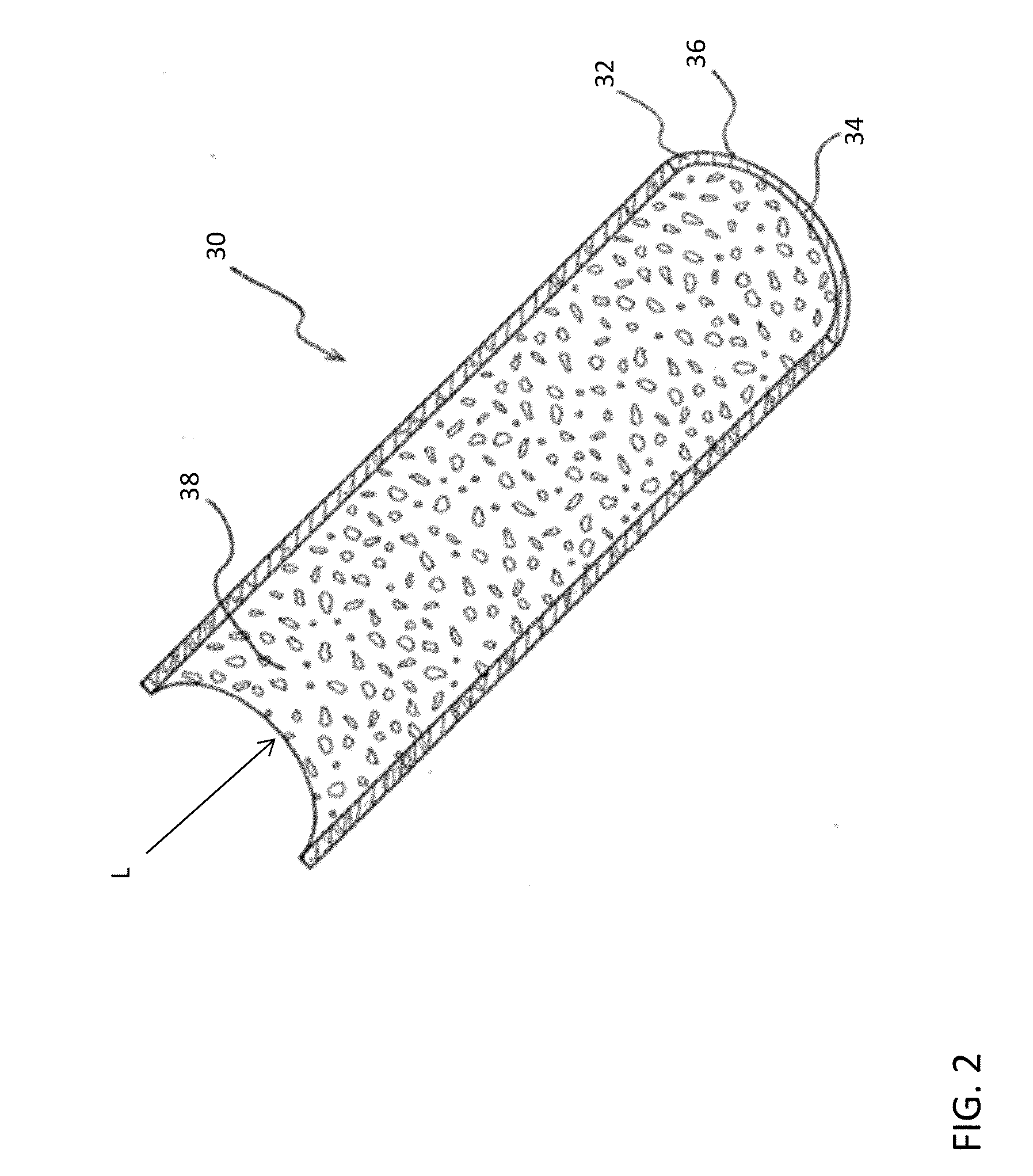
[0012]Referring now to FIG. 1, a cross-section of an exemplary contactor 20, such as a flat panel membrane contactor for example, configured for use in a dehumidification system is illustrated. The schematically illustrated contactor 20 is configured to simultaneously provide heat and / or mass transfer between a hygroscopic material L, such as a liquid desiccant including an aqueous lithium chloride solution for example, and an air flow A, for example outdoor air to be cooled and conditioned prior to being supplied to a building ventilation system. A cross-section of the contactor 20 is shown in simplified form with a housing 22 represented by dashed lines and without inlet ducts, outlet ducts, manifolds, etc . . . . The contactor 20 may include a single contact module 30, or a plurality of similar contact modules 30, for example arranged in a repeating configuration as shown in FIG. 1, such that a channel 40 exists between adjacent contact modules 30. Referring now to FIG. 2, an exe...


PUM


Abstract

A contactor configured for use in a dehumidification system is provided including a plurality of contact modules. Each contact module has a porous membrane that defines an internal space through which a hygroscopic material flows. A membrane property of the porous membrane of at least one contact module is substantially different than the other membranes of the plurality of contact modules.

Description

CROSS-REFERENCE TO RELATED APPLICATIONS[0001]This application claims the benefit of U.S. provisional patent application Ser. No. 61 / 803,643 filed Mar. 20, 2013, the entire contents of which are incorporated herein by reference.BACKGROUND OF THE INVENTION[0002]This invention was made with Government support under Contract No. DE-AR0000147. The Government has certain rights in the invention.BACKGROUND OF THE INVENTION[0003]The invention relates generally to contactors, and more particularly, to porous membrane contactors configured for use in a dehumidification system.[0004]Membrane contactors allow a gaseous phase and a liquid phase, to exchange mass and heat between the phases, without dispersing one phase into the other. A common use for a membrane contactor is the removal or dissolution of gases in a liquid. Examples of conventional contactors include packed towers, flat panel membrane contactors, and tubular contactors. In conventional systems, membrane contactors are operated wi...

Claims


Application Information

Patent Timeline
Patent Type & Authority Applications(United States)
IPC IPC(8): F24F3/14
CPCF24F3/14B01D53/263B01D53/268F24F3/1411B01D53/227B01D2319/06
Inventor SMITH, KENNETH DAVIDMA, ZIDUKANDIL, SHERIF
Owner CARRIER CORP
Learn More