
Lateral flow device for the detection of large pathogens

Inactive Publication Date: 2006-01-26
KIMBERLY-CLARK WORLDWIDE INC
View PDF99 Cites 93 Cited by
  • Summary
  • Abstract
  • Description
  • Claims
  • Application Information

AI Technical Summary

Benefits of technology

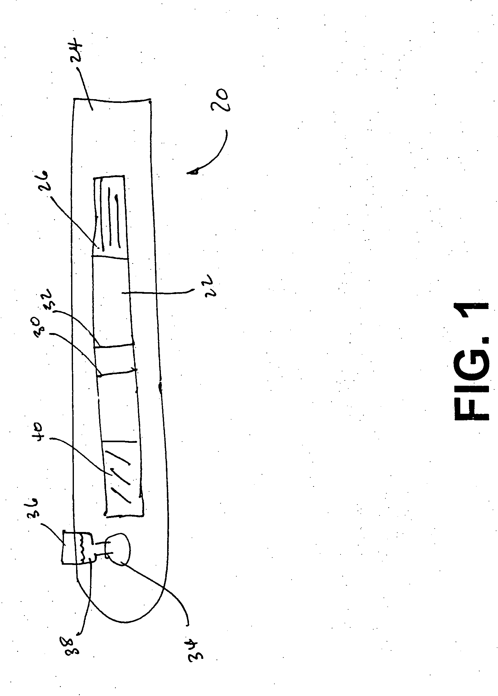
[0009] The control zone is located on the porous membrane downstream from the detection zone. A second capture reagent is immobilized within the control zone that is configured to bind to the conjugate, conjugate-analyte complex or pure probes, to indicate the assay is performing properly. In one embodiment, the second capture reagent is selected from the group consisting of antigens, haptens, protein A or G, neutravidin, avidin, streptavidin, captavidin, primary or secondary antibodies, and complexes thereof.
[0010] The conjugate pad contains detection probes that signal the presence of the analyte. The conjugate pad may also include other, different probe populations, including probes for indication at the control zone. If desired, the detection probes may comprise a substance selected from the group consisting of chromogens, catalysts, luminescent compounds (e.g., fluorescent, phosphorescent, etc.), radioactive compounds, visual labels, liposomes, and combi

Problems solved by technology

Flow through assays have thus far proven of limited use in detection of large pathogens because of the size of the pathogen.
These assays require the movement of the analyte through the device, thus hindering their usefulness with larger, lower mobility, pathogens.
Despite the benefits achieved from these devices, many conventional lateral flow assays encounter significant inaccuracies when exposed to relatively high analyte concentrations and when attempting to detect very large pathogens that are difficult to cause to flow.
Because the uncomplexed analyte is not labeled with a probe, it cannot be detected.
Consequently, if a significant number of the binding sites become occupied by the uncomplexed analyte, the assay may exhibit a “false negative.” This problem is commonly referred to as the “hook effect.” In the case of large pathogens, like, for example, Candida albican, it is likely that the complex will not properly flow to the detection zone on the membrane because of the size of the complex formed.

Method used


Image

  • Lateral flow device for the detection of large pathogens

Examples


Embodiment Construction

[0020] As used herein, the term “analyte” generally refers to a substance to be detected. For instance, analytes may include antigenic substances, haptens, antibodies, and combinations thereof. Analytes include, but are not limited to, toxins, organic compounds, proteins, peptides, microorganisms, amino acids, nucleic acids, hormones, steroids, vitamins, drugs (including those administered for therapeutic purposes as well as those administered for illicit purposes), drug intermediaries or byproducts, bacteria, virus particles and metabolites of or antibodies to any of the above substances. Specific examples of some analytes include ferritin; creatinine kinase MB (CK-MB); digoxin; phenyloin; phenobarbitol; carbamazepine; vancomycin; gentamycin; theophylline; valproic acid; quinidine; luteinizing hormone (LH); follicle stimulating hormone (FSH); estradiol, progesterone; C-reactive protein; lipocalins; IgE antibodies; cytokines; vitamin B2 micro-globulin; glycated hemoglobin (Gly. Hb);...


PUM


Abstract

There is provided a lateral flow assay device for detecting the presence or quantity of an analyte residing in a test sample where the lateral flow assay device has a porous membrane in communication with a conjugate pad and a wicking pad. The porous membrane has a detection zone where a test sample is applied and which has an immobilized first capture reagent configured to bind to at least a portion of the analyte and analyte-conjugate complexes to generate a detection signal. The control zone is located downstream from the detection zone on the porous membrane and has a second capture reagent immobilized within the control zone. The conjugate pad is located upstream from the detection zone, and has detection probes with specific binding members for the analyte. A buffer release zone is located upstream of the conjugate zone and provides for buffer addition to the device, the buffer serving to move the detection probes to the detection and control zones.

Description

BACKGROUND OF THE INVENTION [0001] The diagnosis of large pathogens is currently performed by examining samples under a microscope or by culturing a specimen. Microscopic evaluation requires a trained specialist and an instrument while culturing specimens generally requires a time of more than 24 hours to obtain results. [0002] Flow through assays have thus far proven of limited use in detection of large pathogens because of the size of the pathogen. For example, various analytical procedures and devices are commonly employed in lateral flow assays to determine the presence and / or concentration of smaller analytes that may be present in a test sample. Immunoassays, for example, utilize mechanisms of the immune systems, where antibodies are produced in response to the presence of antigens that are pathogenic or foreign to the organisms. These antibodies and antigens, i.e., immunoreactants, are capable of binding with one another, thereby causing a highly specific reaction mechanism t...

Claims


Application Information

Patent Timeline
IPC IPC(8): G01N33/558
CPCG01N33/558G01N33/53G01N33/569G01N33/54388
Inventor WEI, NINGYANG, SHU-PING
Owner KIMBERLY-CLARK WORLDWIDE INC
Learn More