
Battery separators with cross ribs and related methods

a technology of cross-ribs and separators, which is applied in the manufacture of final products, cell components, cell component details, etc., can solve the problems of unwound reduction of battery efficiency, and achieve the effect of improving bending stiffness

Active Publication Date: 2011-04-21
DARAMIC LLC
View PDF13 Cites 97 Cited by
  • Summary
  • Abstract
  • Description
  • Claims
  • Application Information

AI Technical Summary

Benefits of technology

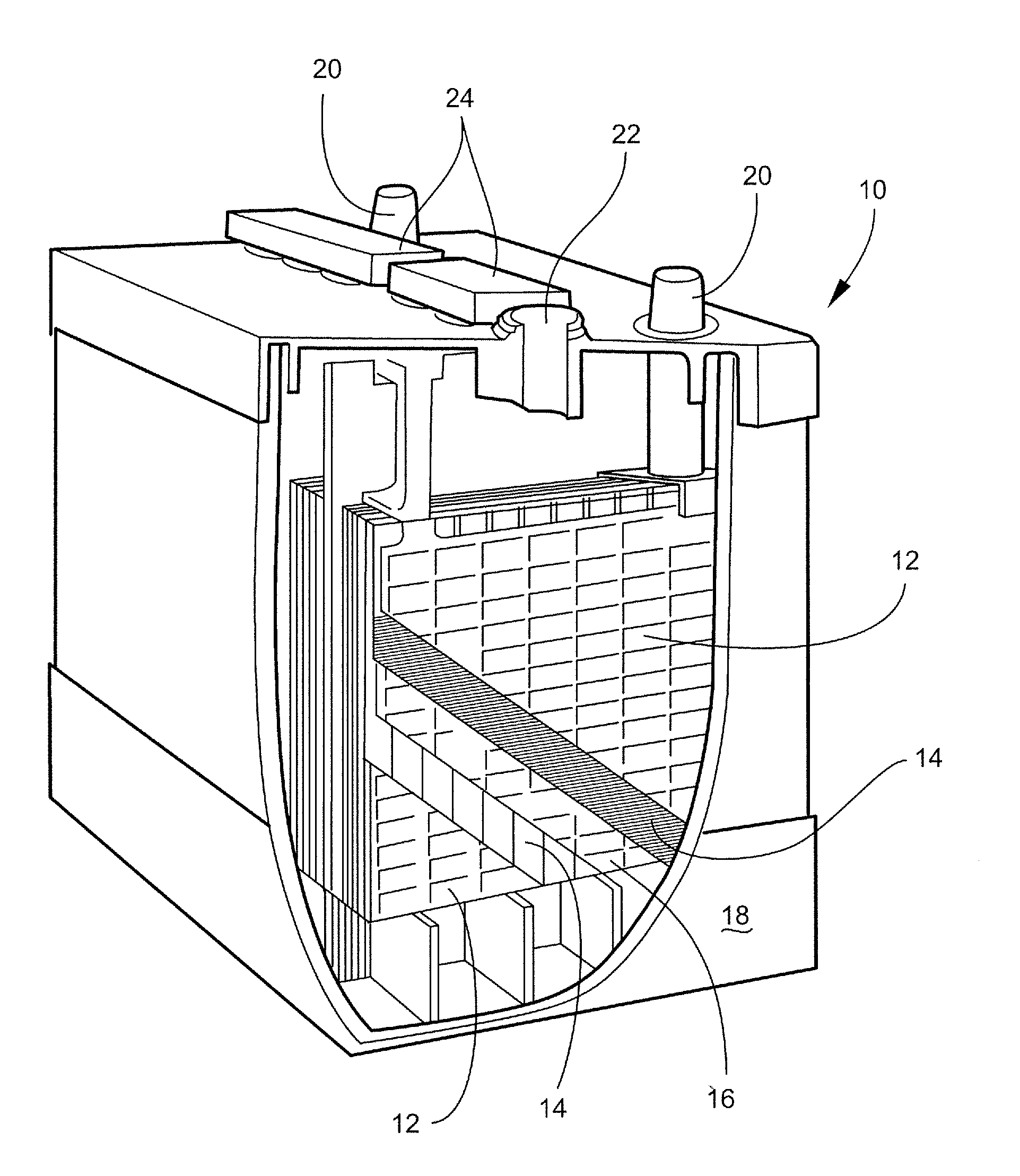
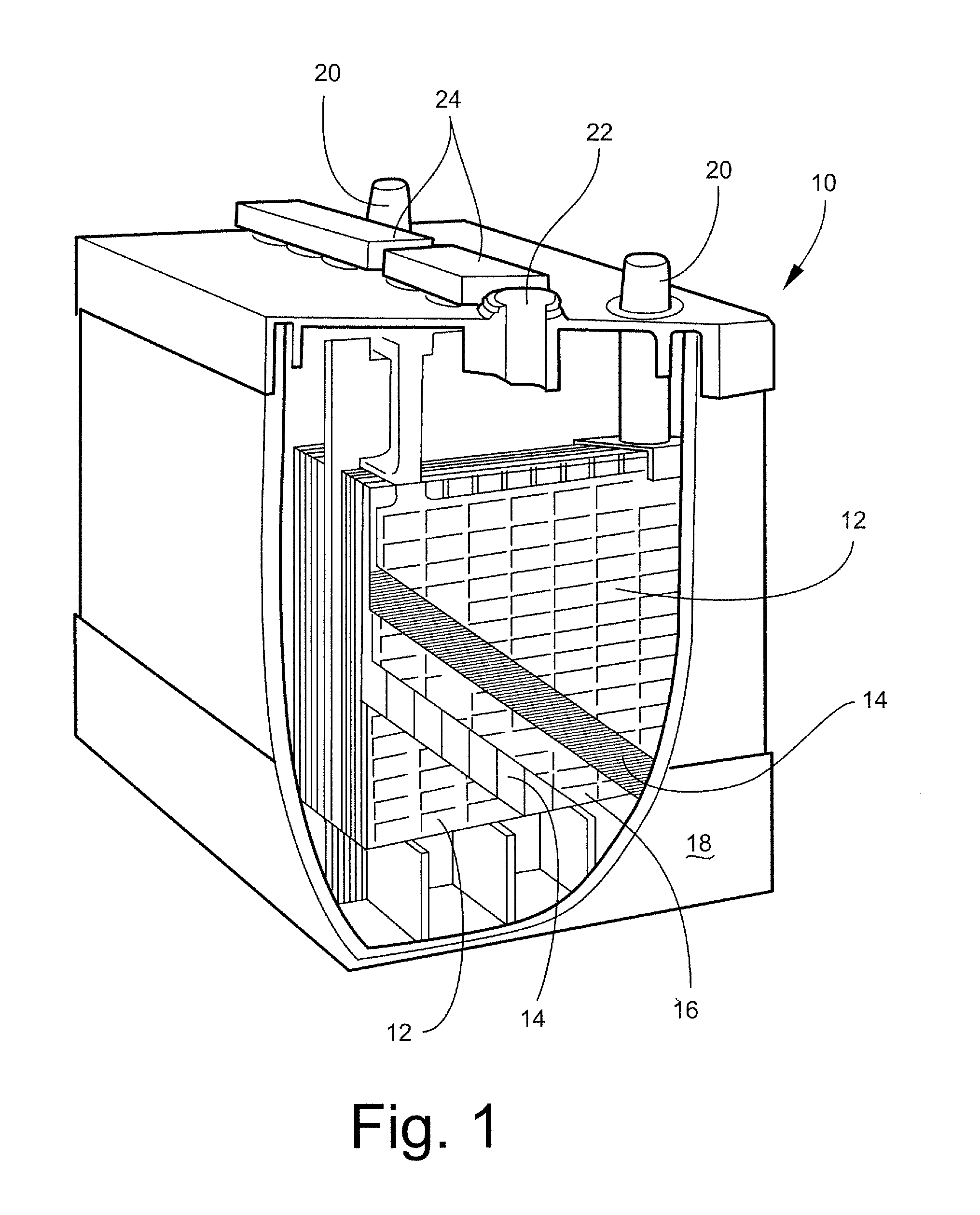
[0009]In accordance with at least certain embodiments, the present invention is directed to improved or specialized battery separators, to methods of manufacture of battery separators, to methods of use of battery separators, to improved battery separators that have cross ribs, and / or to improved separators for lead acid batteries that have cross ribs that are adapted to face the negative electrode and preferably provide improved bending stiffness.
[0012]At least one object of the present invention is the provision of an improved battery separator, improved method of manufacture of a battery separator, improved method of use of a battery separator, and / or improved separators for lead acid batteries that have cross ribs that are adapted to face the negative electrode.
[0013]In accordance with at least selected embodiments, other objects of the present invention may include the provision of improved or specialized battery separators, improved methods of manufacture of battery separators, improved methods of use of battery separators, and / or improved separators for lead acid batteries that have cross ribs that are adapted to face the negative electrode and preferably provide improved bending stiffness.

Problems solved by technology

It was believed that if one were to place other than vertical or longitudinally extending ribs on the negative electrode face of the separator, then the hydrogen gas would be trapped under those ribs, and that this entrapped hydrogen gas would lead to an undesired reduction of efficiency of the battery.

Method used


Image

  • Battery separators with cross ribs and related methods
  • Battery separators with cross ribs and related methods
  • Battery separators with cross ribs and related methods

Examples


examples

[0064]The following examples further illustrate at least selected separator embodiments of the instant invention. NCR refers to the inventive separator with negative cross ribs and Flat Backweb refers to comparative separators devoid of negative cross ribs.

Comparative Data:

[0065]

FlatCharacteristicUnitsNCRBackwebDataset IBackweb ThicknessMils4.76.2Negative Cross RibMils4.50HeightMeasured BW + NCRMils9.26.2ElectricalMohm-6.46.8Resistancein2ER Reduction%5.9Dataset IIBackweb ThicknessMils4.26.2Negative Cross RibMils4.50HeightMeasured BW + NCRmils8.76.2Total Residual Oilwt %14.6514.76Separator Basisg / m298.7109.4WeightBasis Weight%10.84ReductionDataset IIIBackweb Thicknessmils4.06.2Negative Cross Ribmils4.50HeightMeasured BW + NCRmils8.56.2Transverse BendingmN23.316.4StiffnessBending Stiffness%42.07Improvement [(23.3 −Diff16.4) / 16.4]

In accordance with the above datasets, two 6-cell batteries were constructed with 21-plate elements, consisting of 11 negative plates and 10 positive plates. ...


PUM

PropertyMeasurementUnit
porositiesaaaaaaaaaa
pore diametersaaaaaaaaaa
thicknessaaaaaaaaaa

Abstract

A separator for a lead acid battery is a porous membrane having a positive electrode face and a negative electrode face. A plurality of longitudinally extending ribs, a plurality of protrusions or a nonwoven material may be disposed upon the positive electrode face. A plurality of transversely extending ribs are disposed upon the negative electrode face. The transverse ribs disposed upon the negative electrode face are preferably juxtaposed to a negative electrode of the lead acid battery, when the separator is placed within that battery.

Description

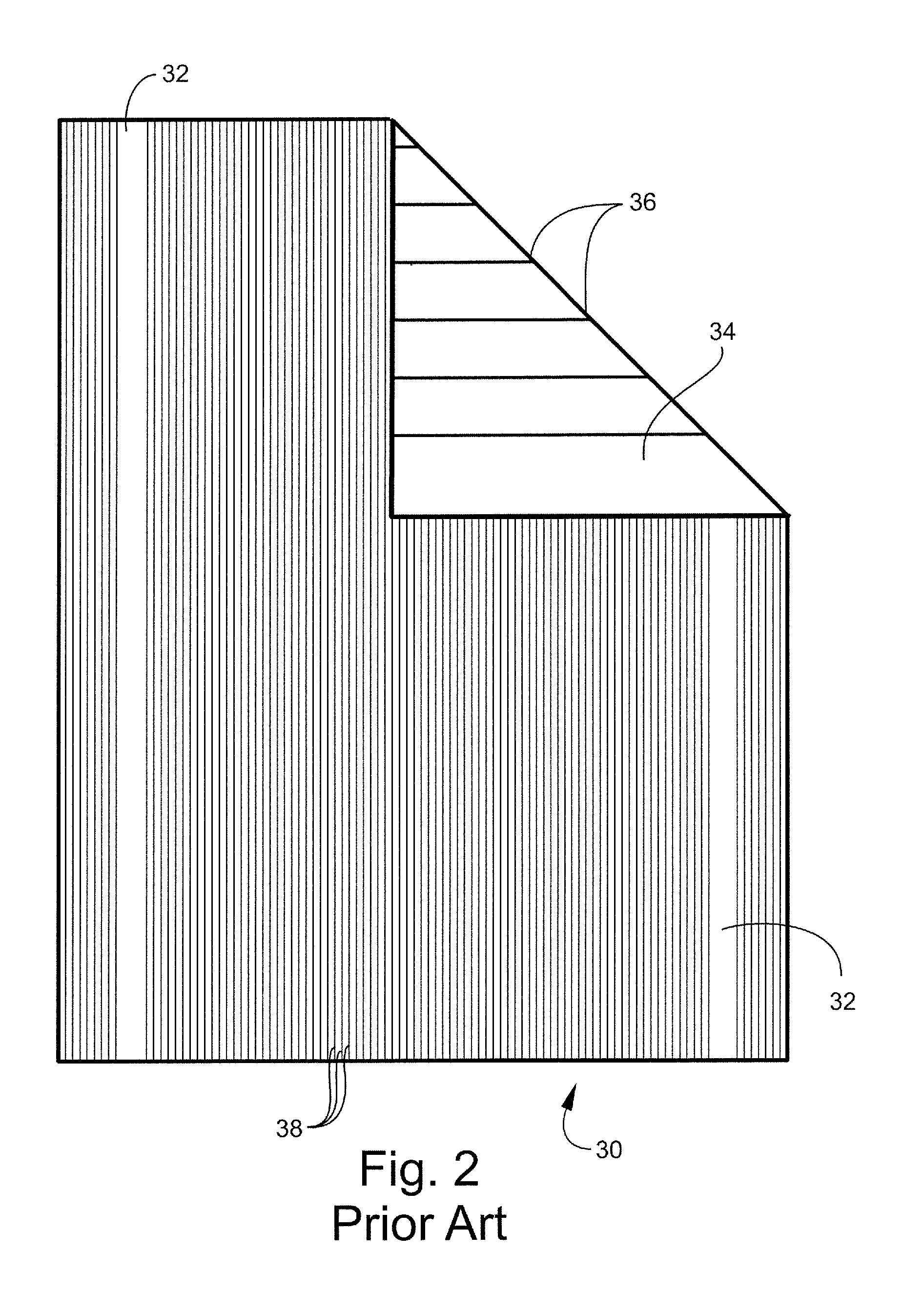
CROSS-REFERENCE TO RELATED APPLICATION[0001]This applications claims priority to and the benefit of U.S. Patent Application Ser. No. 61 / 253,096, filed on Oct. 20, 2009, hereby fully incorporated by reference herein.FIELD OF THE INVENTION[0002]The invention or inventions described hereinbelow is or are directed to battery separators, to methods of manufacture of battery separators, to methods of use of battery separators, to improved battery separators that have cross ribs, and / or to improved separators for lead acid batteries that have cross ribs that are adapted to face the negative electrode.BACKGROUND OF THE INVENTION[0003]Conventional wisdom in the lead acid battery or storage battery art teaches that the negative electrode face of the separator should have either no ribs or ribs that extend in the longitudinal (i.e. vertical or machine) direction. See FIGS. 2 and 3 (discussed below). This understanding is based upon the generation of hydrogen gas at the negative electrode durin...

Claims


Application Information

Patent Timeline
Patent Type & Authority Applications(United States)
IPC IPC(8): H01M2/18H01M50/417H01M50/449H01M50/463H01M50/466H01M50/489H01M50/491
CPCH01M2/162H01M2/1666Y10T29/49108H01M10/06H01M2/18H01M50/463H01M50/466H01M50/417H01M50/491H01M50/449H01M50/489Y02P70/50Y02E60/10H01M50/44H01M50/46H01M50/403H01M10/14
Inventor MILLER, ERIC H.WHEAR, J. KEVIN
Owner DARAMIC LLC
Learn More