Film deposition apparatus

a film deposition and film technology, applied in chemical vapor deposition coatings, metal material coating processes, coatings, etc., can solve the problems of not studying the thermal decomposition of a source gas, not disclosing the problem of high dielectric film deposition, and difficult to reduce the adhesion of attached decomposed matter

Active Publication Date: 2014-10-02
TOKYO ELECTRON LTD
View PDF72 Cites 194 Cited by
  • Summary
  • Abstract
  • Description
  • Claims
  • Application Information

AI Technical Summary

Benefits of technology

[0008]Embodiments of the present invention provide a novel and useful film deposition apparatus solving one or more of the problems discussed above.

Problems solved by technology

When the decomposed matter is attached to the inner wall of the gas injector, the decomposed matter is likely to cause particles by being released from the inner wall in the middle of the film deposition process.
Hence, there is a trade-off between depositing a high-quality high dielectric film and reducing adhesion of the attached decomposed matter within the gas injector, and it is very difficult to reduce the adhesion of the attached decomposed matter while depositing a high-quality thin film.
However, these patent documents do not study the thermal decomposition of a source gas when depositing a thin film by the ALD method.
Moreover, Japanese Laid-Open Patent Application Publication No. 2011-100956 discloses an example of combining a rectifying member with an apparatus including the above-mentioned turntable, but does not disclose a problem in depositing a high dielectric film.

Method used


Image

  • Film deposition apparatus
  • Film deposition apparatus
  • Film deposition apparatus

Examples


Embodiment Construction

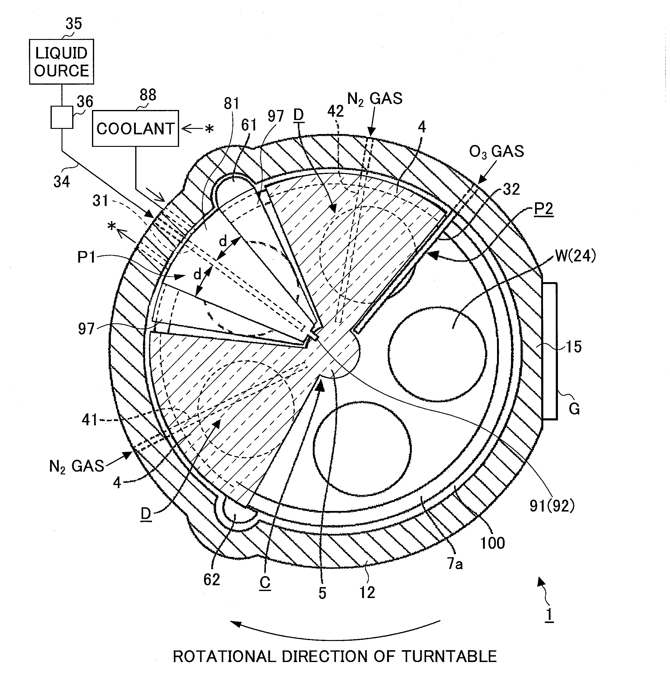
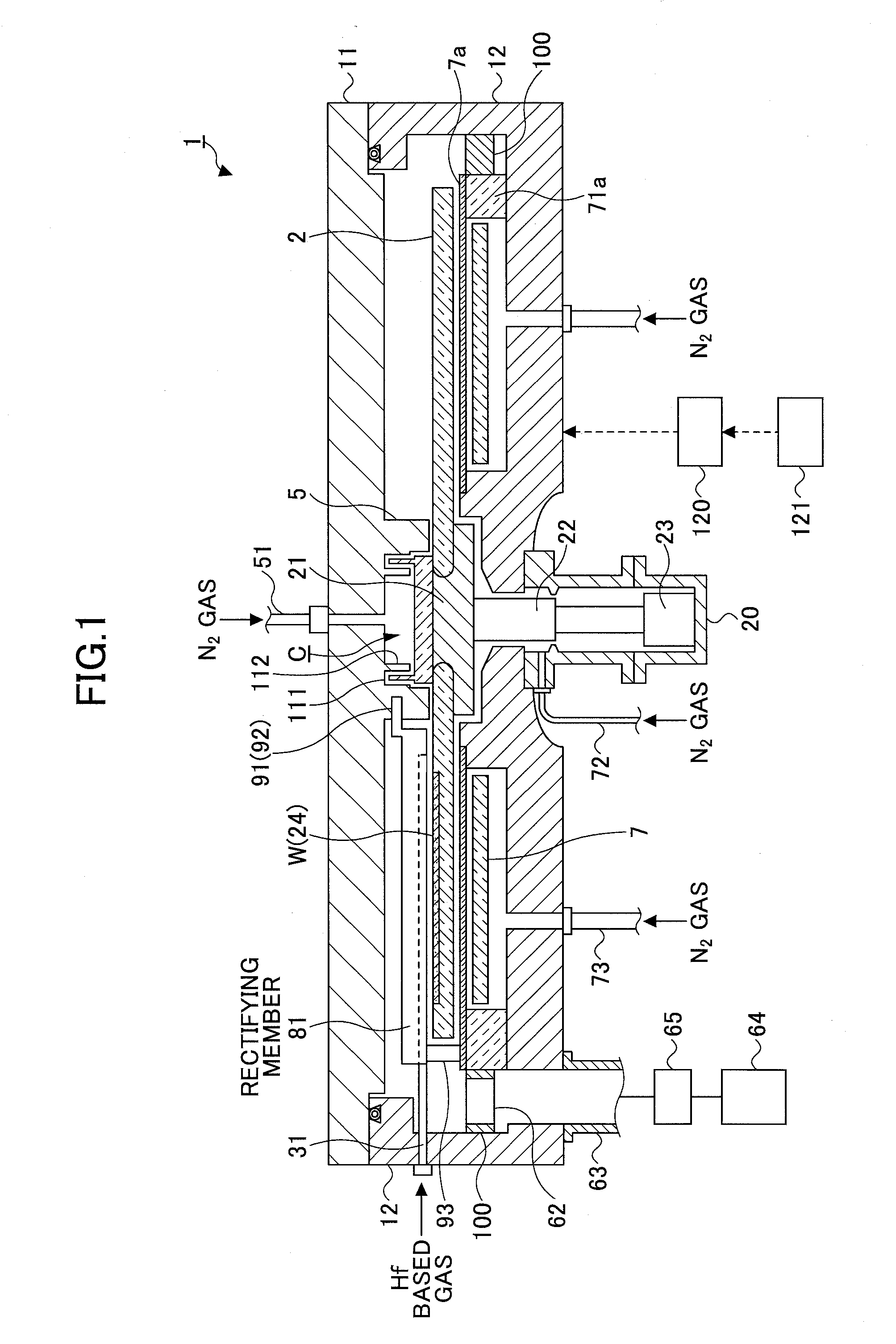
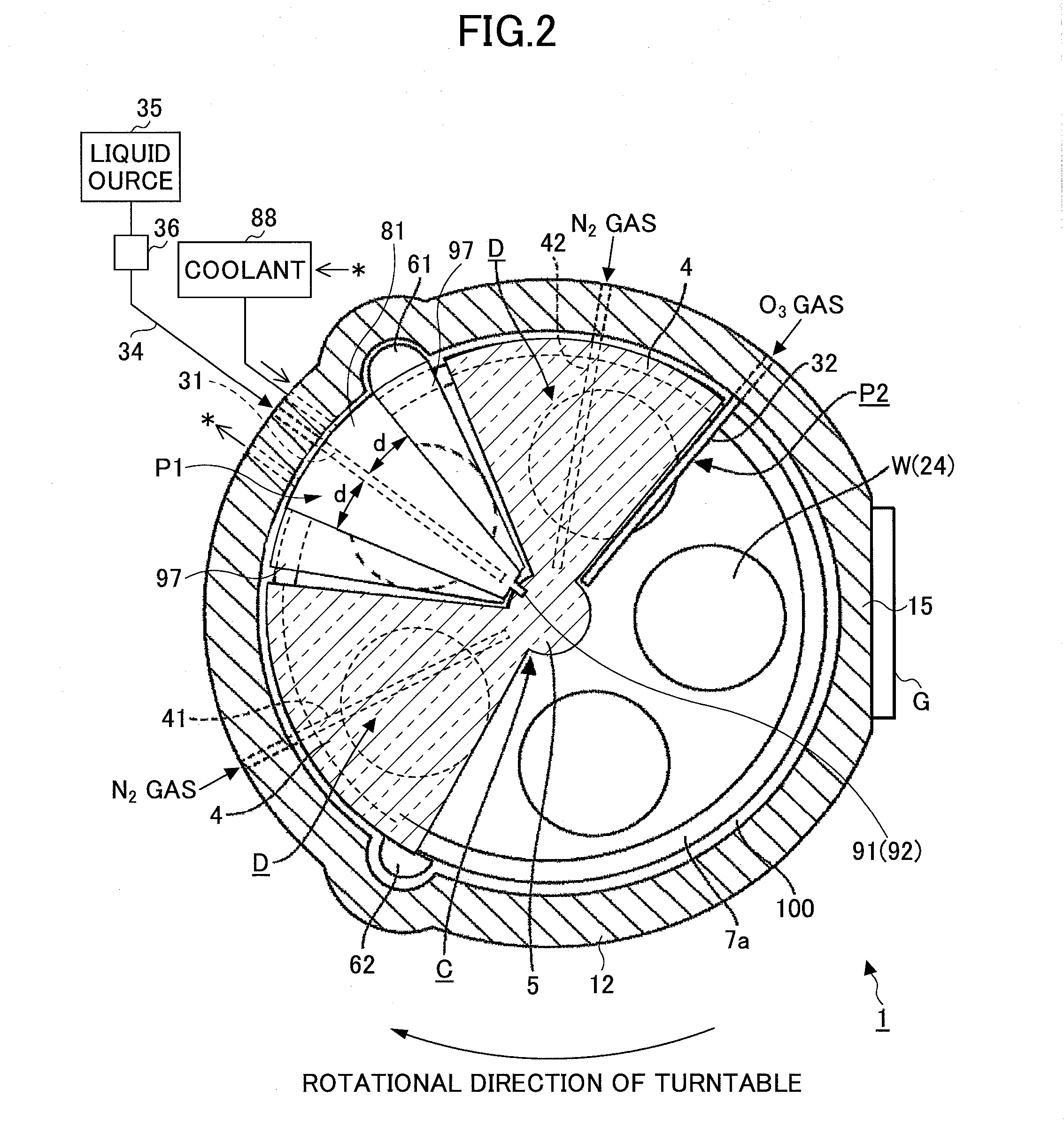
[0028]A description is given below of an example of a film deposition apparatus of an embodiment of the present invention, with reference to FIGS. 1 through 5. As shown in FIGS. 1 and 2, this film deposition apparatus includes a vacuum chamber 1 having an approximately circular planar shape, and a turntable 2 provided in the vacuum chamber 1, having a rotational center that coincides with a center of the vacuum chamber 1. The film deposition apparatus is configured to deposit a film such as a hafnium oxide film by alternately supplying two kinds of process gases that react with each other onto a wafer W. The film deposition apparatus, as described in detail later, prevents a source gas from pyrolytically decomposing on a surface of a gas injector that supplies the source gas while performing a deposition process at a decomposition temperature or higher of the source gas. Hereinafter, a description is given of a specific configuration of the film deposition apparatus.

[0029]A separati...


PUM

PropertyMeasurementUnit
diameteraaaaaaaaaa
pressureaaaaaaaaaa
distanceaaaaaaaaaa

Abstract

In discharging a source gas from a first process gas nozzle, rectifying members including a coolant flow passage provided in a concertinaing manner therein are arranged both sides of the first process gas nozzle. Then, a coolant at a temperature higher than a liquefaction temperature of the source gas and lower than a thermal decomposition temperature of the source gas is flown through the coolant flow passage, by which the first process gas nozzle is cooled through the rectifying member.

Description

CROSS-REFERENCE TO RELATED APPLICAITONS[0001]This patent application is based upon and claims the benefit of priority of Japanese Patent Application No. 2013-69414, filed on Mar. 28, 2013, the entire contents of which are incorporated herein by reference.BACKGROUND OF THE INVENTION[0002]1. Field of the Invention[0003]The present invention relates to a film deposition apparatus that deposits a thin film on a substrate by supplying a plurality of process gases that react with each other to the substrate in turn.[0004]2. Description of the Related Art[0005]A process is known that alternately supplies a plurality of, for example, two kinds of process gases that react with each other to a substrate such as a semiconductor wafer (which is hereinafter called “wafer”) as a method of depositing a high dielectric film such as hafnium oxide (Hf—O) on the substrate. In this method, a thin film is formed by depositing an atomic layer or a molecular layer on the wafer in a layer-by-layer manner, ...

Claims


Application Information

Patent Timeline
Patent Type & Authority Applications(United States)
IPC IPC(8): C23C16/44
CPCC23C16/4402C23C16/4401C23C16/45551C23C16/45572
Inventor WAMURA, YUKUWAMOTO, TOMONORI
Owner TOKYO ELECTRON LTD
Why Eureka
Try Eureka