
Reticle pod having gas guiding apparatus

Active Publication Date: 2014-10-02
GUDENG PRECISION IND CO LTD
View PDF3 Cites 5 Cited by
  • Summary
  • Abstract
  • Description
  • Claims
  • Application Information

AI Technical Summary

Benefits of technology

The present invention provides a reticle pod with gas guiding apparatus to improve the efficiency of cleaning the reticle using high-purity gas. This allows for a reduction in the usage of the gas and increases in the filling efficiency, resulting in cost savings and improved production efficiency.

Problems solved by technology

Any dust, particle, or organic matter adhered to reticles will deteriorate the quality of the projected images.
Nonetheless, current clean rooms cannot achieve the absolutely dust-free condition.
Thereby, the distribution of the high-purity gas in the reticle pod is nonuniform and hence the cleaning effect of the high-purity gas for the reticle pod is inferior; the high-purity gas has to be filled continuously into the reticle pod until the reticle is completely cleaned.
Consequently, the usage of the high-purity has is increased, and the efficiency of filling high-purity gas into reticle pods is inferior.

Method used


Image

  • Reticle pod having gas guiding apparatus
  • Reticle pod having gas guiding apparatus
  • Reticle pod having gas guiding apparatus

Examples


first embodiment

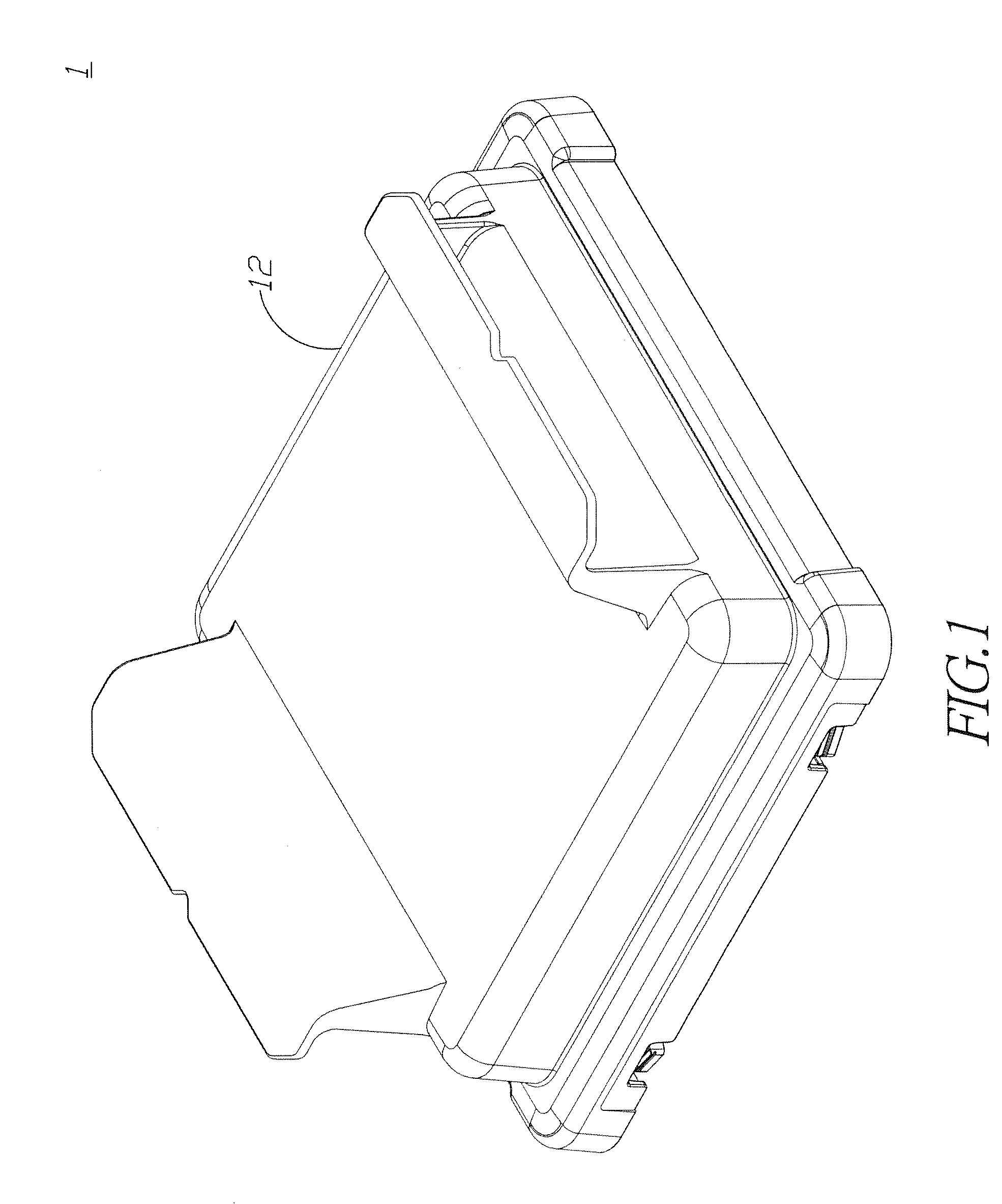
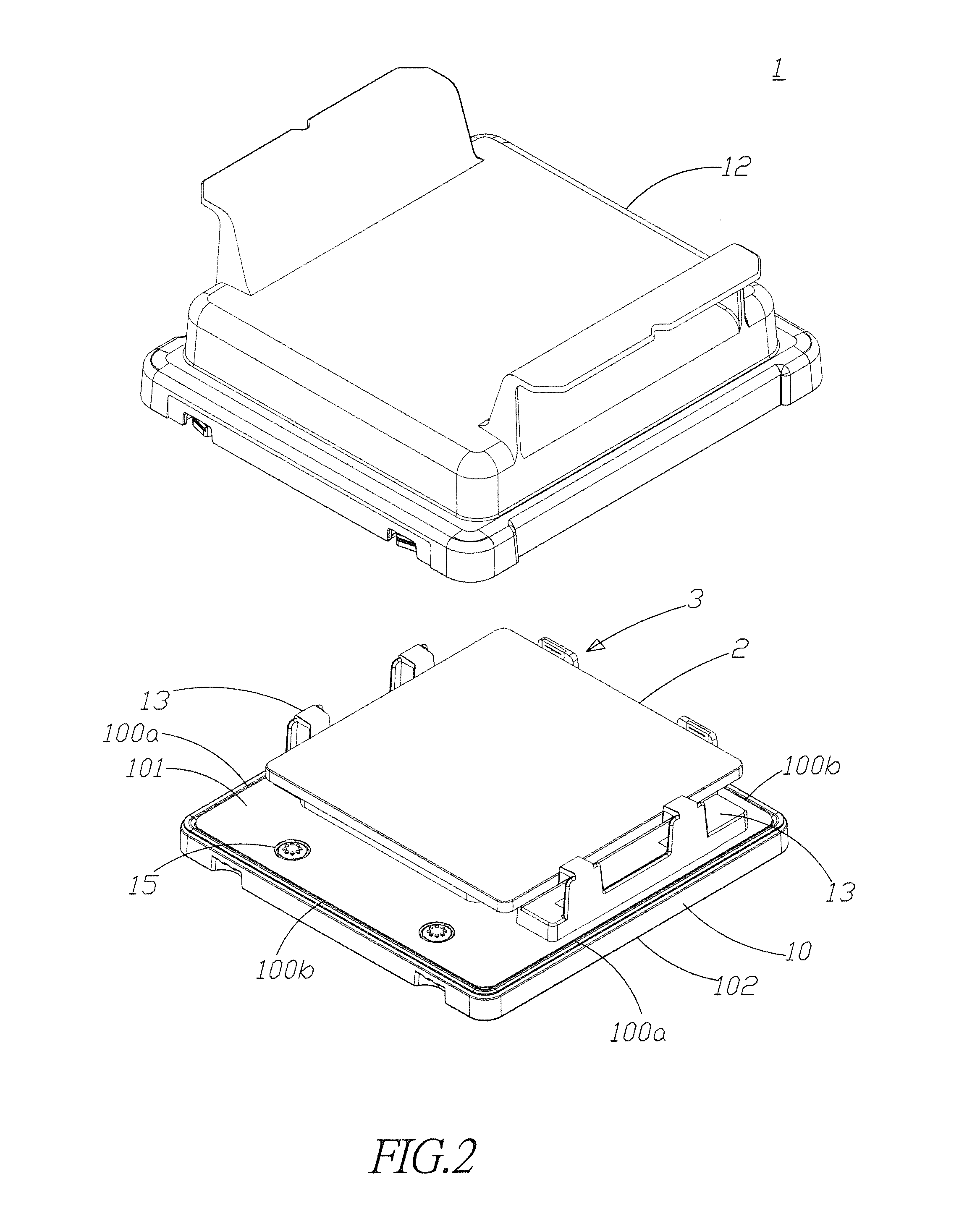
[0024]FIGS. 1 to 3 show an appearance diagram, an assembly diagram, and a cross-sectional view of the reticle pod according to the present invention. As shown in the figures, the present embodiment provides a reticlereticle pod 1, which comprises a base 10 and a cover 12. The cover 12 is disposed over the base 10 and forming an accommodating space 11 between the cover 12 and the base 10. The accommodating space is used for accommodating a reticle 2. The base 10 has two opposing first sides 100a and two opposing second sides 100b. The base 10 has a first surface 101 facing the accommodating space 11; two positioning members 13 are disposed on the first surface 101 of the base 10. The two positioning members 13 are disposed oppositely and adjacent to the two first sides 100a of the base 10, respectively. The base 10 has two inlets 14. Each inlet 14 penetrates from a second surface 102, which faces the outside of the reticle 1, of the base 10 to the first surface 101 of the base 10. Th...

second embodiment

[0039]FIG. 6A and FIG. 6B show an appearance diagram and an assembly diagram of the gas guiding apparatus according to the present invention. As shown in the figures, the difference between the present embodiment and the previous one is that the reticle pod 1 according to the previous embodiment has two gas guiding apparatuses 3 with each gas guiding apparatus 3 corresponding to an inlet 14. Nonetheless, the reticle pod 1 according to the present embodiment has only one gas guiding apparatus 3 corresponding to two inlets 14 simultaneously. Because the gas guiding apparatus 3 needs to correspond to two inlets 14 simultaneously, the structures of the guiding body 31 and the cap 32 are different from the ones according to the previous embodiment.

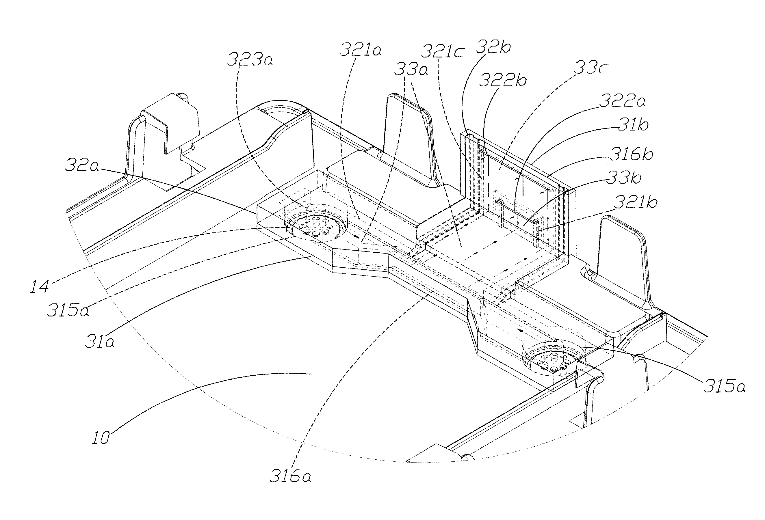
[0040]The first body 31a of the guiding body 31 according to the present embodiment has two holes 315a corresponding to the two inlets 14, respectively. The first surface 313a of the first body 31a has the T-shapes first accommodating trench 31...


PUM


Abstract

The present invention relates to a reticle pod having gas guiding apparatus. The gas guiding apparatus communicates with at least an inlet of the reticle pod and comprises a first outlet corresponding to a first gas flowing space of the reticle pod and a second outlet corresponding to a second gas flowing space. When the inlet supplies a high-purity gas to the gas guiding apparatus, the high-purity gas will flows through the gas guiding apparatus, and flow to the first and second gas flowing spaces via the first and second outlets, respectively to distribute uniformly in the first and second gas flowing spaces. In addition, the cleaning efficiency on the reticle is improved; the contact between the reticle and air can be avoided for protecting the reticle. Thereby, the usage of the high-purity gas is reduced, and the filling efficiency of the high-purity gas is enhanced.

Description

FIELD OF THE INVENTION[0001]The present invention relates generally to a reticle pod, and particularly to a reticle pod having gas guiding apparatus.BACKGROUND OF THE INVENTION[0002]Semiconductor technologies are developing rapidly in recent years. Especially, the lithography technology plays an important role in pattern definition. The application of the lithography technology in semiconductor is to fabricate transparent reticles with specific shapes according to the designed circuit. By using the exposure principle, light passes through reticles and projected to silicon wafers. After exposure, specific patterns are formed. Any dust, particle, or organic matter adhered to reticles will deteriorate the quality of the projected images. Thereby, the reticles used for generating patterns need to be kept absolutely clean. Accordingly, in general wafer fabrication processes, the environment of clean room is provided for avoiding pollution of the particles in the air. Nonetheless, current...

Claims


Application Information

Patent Timeline
IPC IPC(8): H01L21/673
CPCH01L21/67389H01L21/67359H01L21/67393
Inventor LU, PAO-YILIN, TIEN-JUI
Owner GUDENG PRECISION IND CO LTD
Features
  • Generate Ideas
  • Intellectual Property
  • Life Sciences
  • Materials
  • Tech Scout
  • Unparalleled Data Quality
  • Higher Quality Content
  • 60% Fewer Hallucinations
Learn More