
Transducer apparatus

a technology of transducer and transducer body, which is applied in the direction of diaphragm construction, electrostatic transducer, miconductor, etc., can solve the problem of wind noise limitation, inability to adapt to the use later for a specific purpose, and limit the modification of the acoustic response of the transducer

Active Publication Date: 2014-10-02
NOKIA TECHNOLOGLES OY
View PDF2 Cites 26 Cited by
  • Summary
  • Abstract
  • Description
  • Claims
  • Application Information

AI Technical Summary

Benefits of technology

The aim of the invention is to solve one or more problems that were previously present.

Problems solved by technology

In known acoustic transducer configurations, the mechanical design of the sound channels is fixed at the point of hardware design and manufacture of the device is completed, and cannot be later adapted during use for a specific purpose or desired configuration.
Furthermore there is a limit to the modification of the acoustic response of the transducer which can be carried out in the DSP.
An example of the limitations of the mechanical design of typical microphone transducers is that of wind noise.
Wind noise is a problem particularly for miniaturised designs such as found in mobile phone where there is no room for mechanical protection of the microphone from wind such as used in broadcast microphones like wind screens or foam protectors.
Furthermore filtering out the wind noise from the signal in the electrical domain, not only requires significant processing power in a digital signal processor, but typically produces poor results as the sound pressure levels generated by the wind cause the microphone acoustic element to saturate.

Method used


Image

  • Transducer apparatus
  • Transducer apparatus
  • Transducer apparatus

Examples


Embodiment Construction

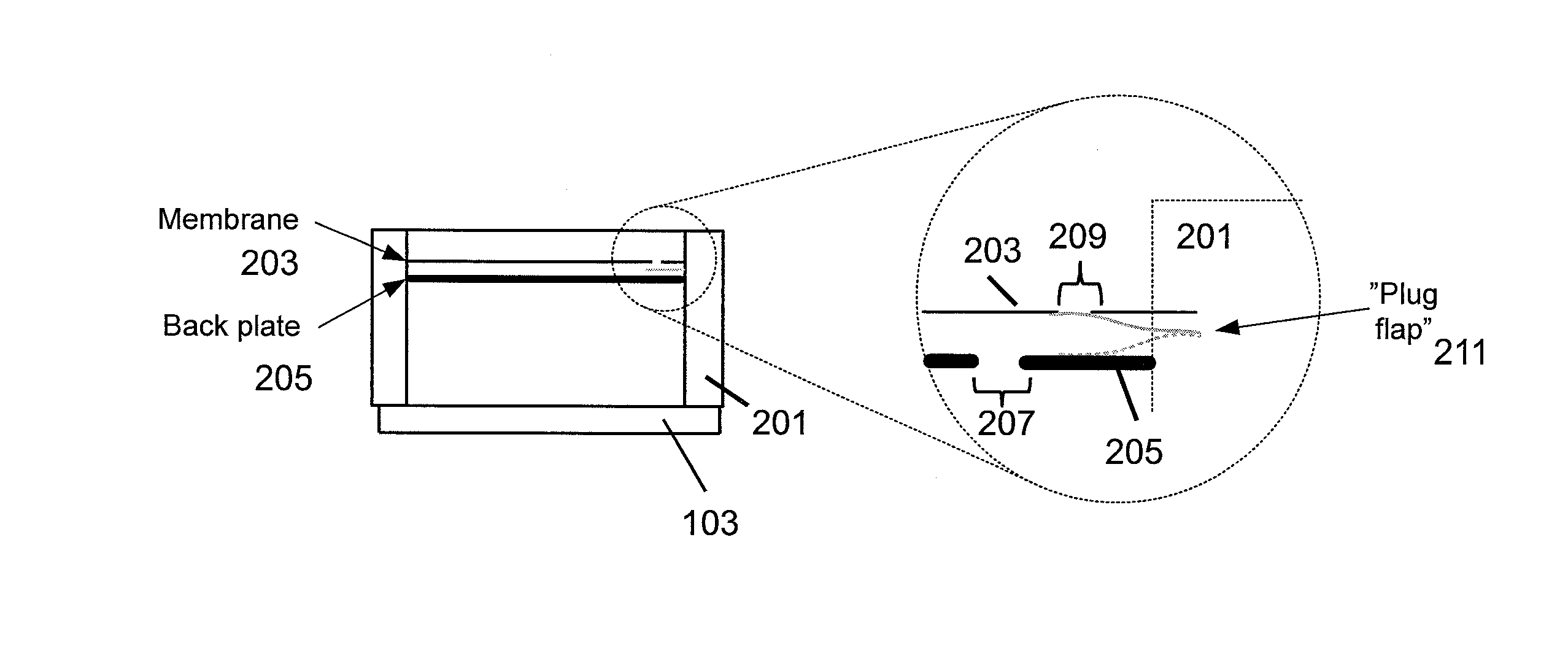
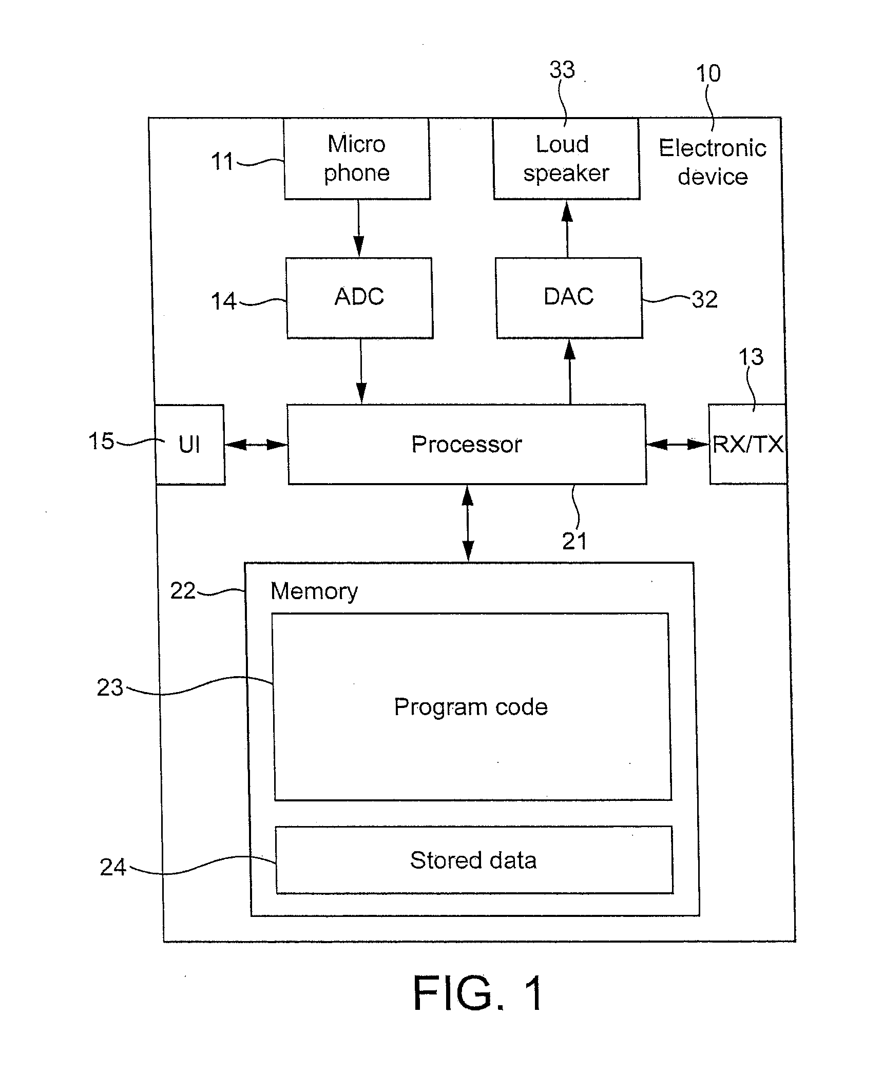
[0045]The following describes in further detail suitable apparatus and possible mechanisms for the provision of transducers having changeable acoustic properties. In this regard reference is first made to FIG. 1 which shows a schematic block diagram of an exemplary apparatus or electronic device 10, which may incorporate transducers having changeable acoustic properties according to some embodiments. In the following examples and embodiments the transducer receives or generates an analogue signal which is processed by an associated analogue to digital converter, however it would be understood that in some embodiments the microphone / speaker is an integrated transducer generating digital or receiving digital signals directly. Furthermore in some embodiments the transducer mechanical filter is a pure analogue design, in other words processing is performed in the analogue domain with respect to the mechanical acoustic filter.

[0046]The electronic device 10 may for example be a mobile ter...


PUM


Abstract

An acoustic transducer comprising: a mechanical acoustic filter configured to be electrically controllable to change the acoustic properties of the transducer.

Description

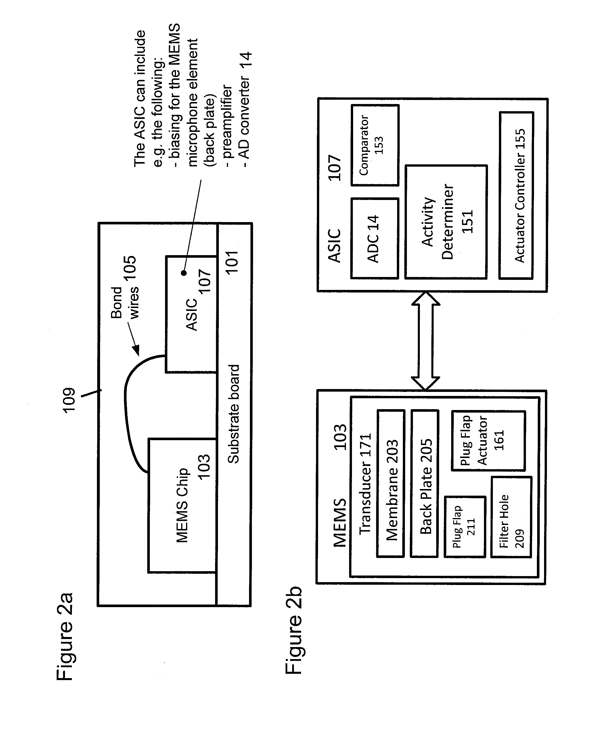
FIELD OF THE APPLICATION[0001]The present invention relates to a transducer apparatus. The invention further relates to, but is not limited to, a transducer apparatus for use in mobile devices.BACKGROUND OF THE APPLICATION[0002]Many portable devices, for example mobile telephones, contain a number of acoustic transducers, such as microphones, earpieces and speakers. Such transducers are key components in mobile phone audio / acoustic design. Generally, there will be one or more sound channels or back cavities associated with each acoustic transducer. Such sound channels can ensure a certain frequency response is obtained for the transducer, and must be carefully designed as part of the mechanical configuration of the device hardware. Small changes in the size and configuration of the sound channels or cavities can have a large effect on the acoustic properties of the combined transducer / sound channel.[0003]In known acoustic transducer configurations, the mechanical design of the sound...

Claims


Application Information

Patent Timeline
Patent Type & Authority Applications(United States)
IPC IPC(8): H04R1/28H04R3/00
CPCH04R3/00H04R1/28H04M1/03H04R1/083H04R1/222H04R7/04H04R19/005H04R2410/07H04M1/035H04R2201/003H01L2224/48137H01L2924/181H01L2224/48091H01L2924/00014H01L2924/00012H04R19/00H04R1/22H04R7/26
Inventor SUVANTO, MIKKO VELI AIMOREHDER, JORG
Owner NOKIA TECHNOLOGLES OY
Learn More