Wide temperature range optical fiber connector with thermal expansion compensation

a technology of thermal expansion compensation and optical fiber, which is applied in the direction of optical elements, electromagnetic transceivers, instruments, etc., can solve the problems of high operating temperature range, high cost of systems, and insufficient bandwidth of optical fibers, etc., to achieve high bandwidth, low cost, and high bandwidth

Active Publication Date: 2014-10-02
MOLEX INC
View PDF13 Cites 54 Cited by
  • Summary
  • Abstract
  • Description
  • Claims
  • Application Information

AI Technical Summary

Benefits of technology

[0002]The Present Disclosure relates generally to optical fiber assemblies and, more particularly, to an optical fiber cable assembly for use within a wide temperature range and having thermal expansion compensation functionality.
[0003]It is often desirable to use optical fiber systems for signal transmission in high bandwidth applications. However, the use of optical fibers may create challenges in environments having significant ranges of operating temperatures. Automotive applications that operate within the engine compartment are subjected to relatively high and low temperatures. While some optical fiber systems may be operational within the required temperature range, such systems are often too expensive for high volume automotive applications. Lower cost systems, such as those that utilize plastic optical fiber, typically are not able to operate effectively within the required operational temperature range. In addition, plastic optical fiber systems may not have sufficient bandwidth for some applications. Accordingly, a relatively low cost, high bandwidth optical fiber system that is operational within a wide range of temperatures is desirable.

Problems solved by technology

However, the use of optical fibers may create challenges in environments having significant ranges of operating temperatures.
Automotive applications that operate within the engine compartment are subjected to relatively high and low temperatures.
While some optical fiber systems may be operational within the required temperature range, such systems are often too expensive for high volume automotive applications.
Lower cost systems, such as those that utilize plastic optical fiber, typically are not able to operate effectively within the required operational temperature range.
In addition, plastic optical fiber systems may not have sufficient bandwidth for some applications.

Method used


Image

  • Wide temperature range optical fiber connector with thermal expansion compensation
  • Wide temperature range optical fiber connector with thermal expansion compensation
  • Wide temperature range optical fiber connector with thermal expansion compensation

Examples


Embodiment Construction

[0010]While the Present Disclosure may be susceptible to embodiment in different forms, there is shown in the Figures, and will be described herein in detail, specific embodiments, with the understanding that the disclosure is to be considered an exemplification of the principles of the Present Disclosure, and is not intended to limit the Present Disclosure to that as illustrated.

[0011]In the embodiments illustrated in the Figures, representations of directions such as up, down, left, right, front and rear, used for explaining the structure and movement of the various elements of the Present Disclosure, are not absolute, but relative. These representations are appropriate when the elements are in the position shown in the Figures. If the description of the position of the elements changes, however, these representations are to be changed accordingly.

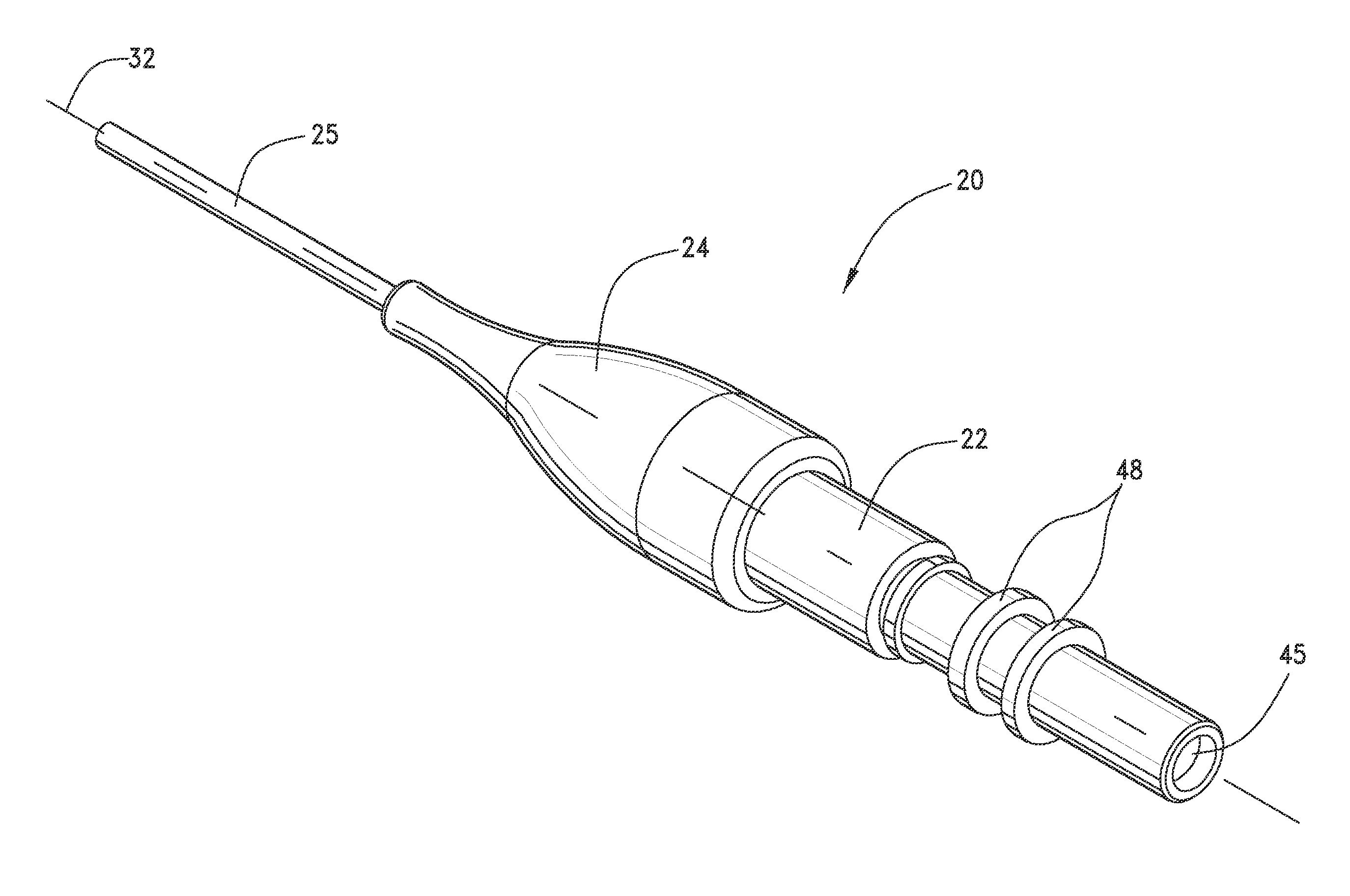
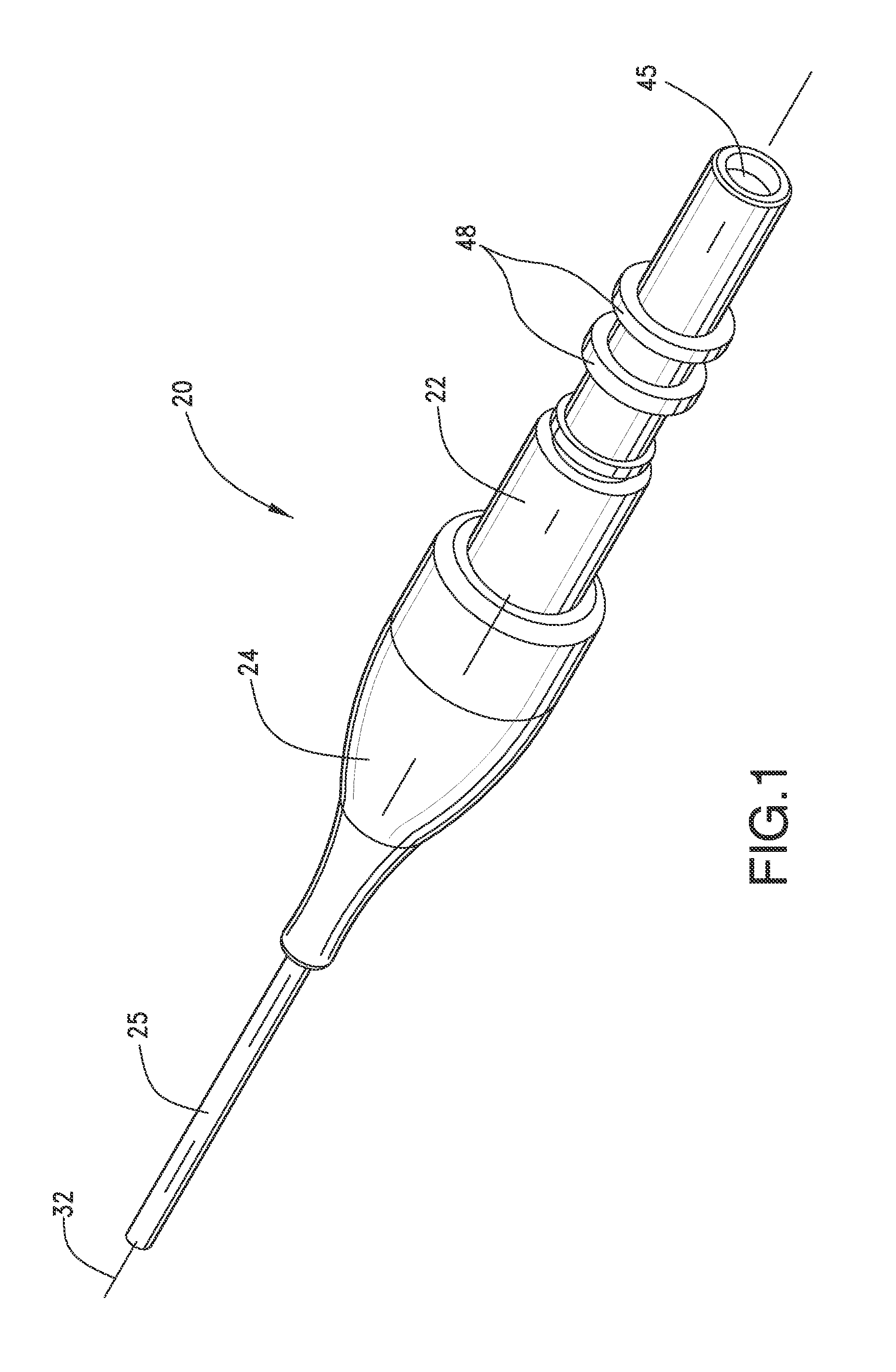
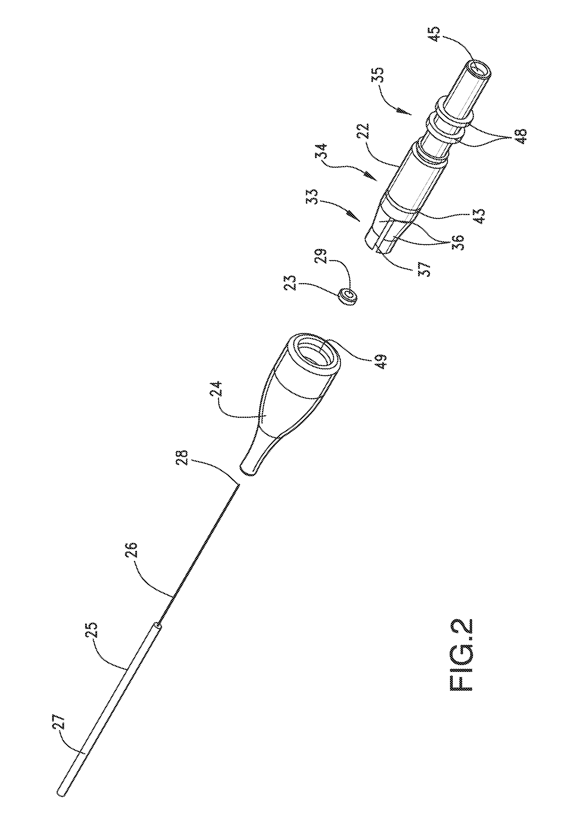
[0012]Referring to FIGS. 1-5, an optical fiber cable assembly 20 with thermal expansion compensation is illustrated. Optical fiber cabl...


PUM


Abstract

An optical fiber assembly comprises an optical fiber having a forward end, a ferrule supporting the optical fiber, a beam expanding element aligned with the forward end of the optical fiber, and a thermal expansion compensation element adjacent the optical fiber to compensate for thermal expansion differences between the optical fiber and the ferrule.

Description

REFERENCE To RELATED APPLICATIONS[0001]The Present Disclosure claims priority to previously-filed U.S. Provisional Patent Application No. 61 / 560,041, entitled “Wide Temperature Range Optical Fiber Connector With Thermal Expansion Compensation,” and filed on 15 Nov. 2011. The content of the aforementioned Application is hereby incorporated by reference in its entirety herein.BACKGROUND AND SUMMARY OF THE PRESENT DISCLOSURE[0002]The Present Disclosure relates generally to optical fiber assemblies and, more particularly, to an optical fiber cable assembly for use within a wide temperature range and having thermal expansion compensation functionality.[0003]It is often desirable to use optical fiber systems for signal transmission in high bandwidth applications. However, the use of optical fibers may create challenges in environments having significant ranges of operating temperatures. Automotive applications that operate within the engine compartment are subjected to relatively high and...

Claims


Application Information

Patent Timeline
Patent Type & Authority Applications(United States)
IPC IPC(8): H04B10/2575H04B10/40G02B6/38
CPCH04B10/2575H04B10/40G02B6/3853G02B6/381G02B6/3823G02B6/3865G02B6/4262G02B6/4293G02B6/3829G02B6/3888
Inventor WALDRON, MARKHODGE, MALCOLM H.CHEN, WENZONGRICHARDSON, DEAN A.ARMAND, JANNICKGARDNER, MICHAEL J.
Owner MOLEX INC
Why Eureka
Try Eureka