Membrane electrode assembly

Active Publication Date: 2014-10-02
HONDA MOTOR CO LTD
View PDF7 Cites 2 Cited by
  • Summary
  • Abstract
  • Description
  • Claims
  • Application Information

AI Technical Summary

Benefits of technology

The fuel cell described in this patent operates by using a membrane electrode assembly to generate electric power. When the fuel cell is operating, oxygen-containing gas and fuel gas are supplied to the fuel cell, and a coolant is supplied to the coolant inlet passage. The coolant flows through the coolant flow field and cools the entire power generation surface of the membrane electrode assembly before being discharged. The oxygen-containing gas and fuel gas flow through their respective flow fields and react with each other in the electrodes to generate electric power. The patent describes a fuel cell with a unique membrane electrode assembly that has improved performance and efficiency.

Problems solved by technology

On the other hand, when the water retention ability is excessively increased, a so-called flooding is caused.
In each case, the power generation property of the fuel cell is deteriorated.
In Japanese Laid-Open Patent Publication Nos. 2010-040377, 2010-146769, and 2005-332672, even in the case of forming the additional layer, retention of the power generation property of the fuel cell is not sufficiently considered.

Method used


Image

  • Membrane electrode assembly
  • Membrane electrode assembly
  • Membrane electrode assembly

Examples


example 1

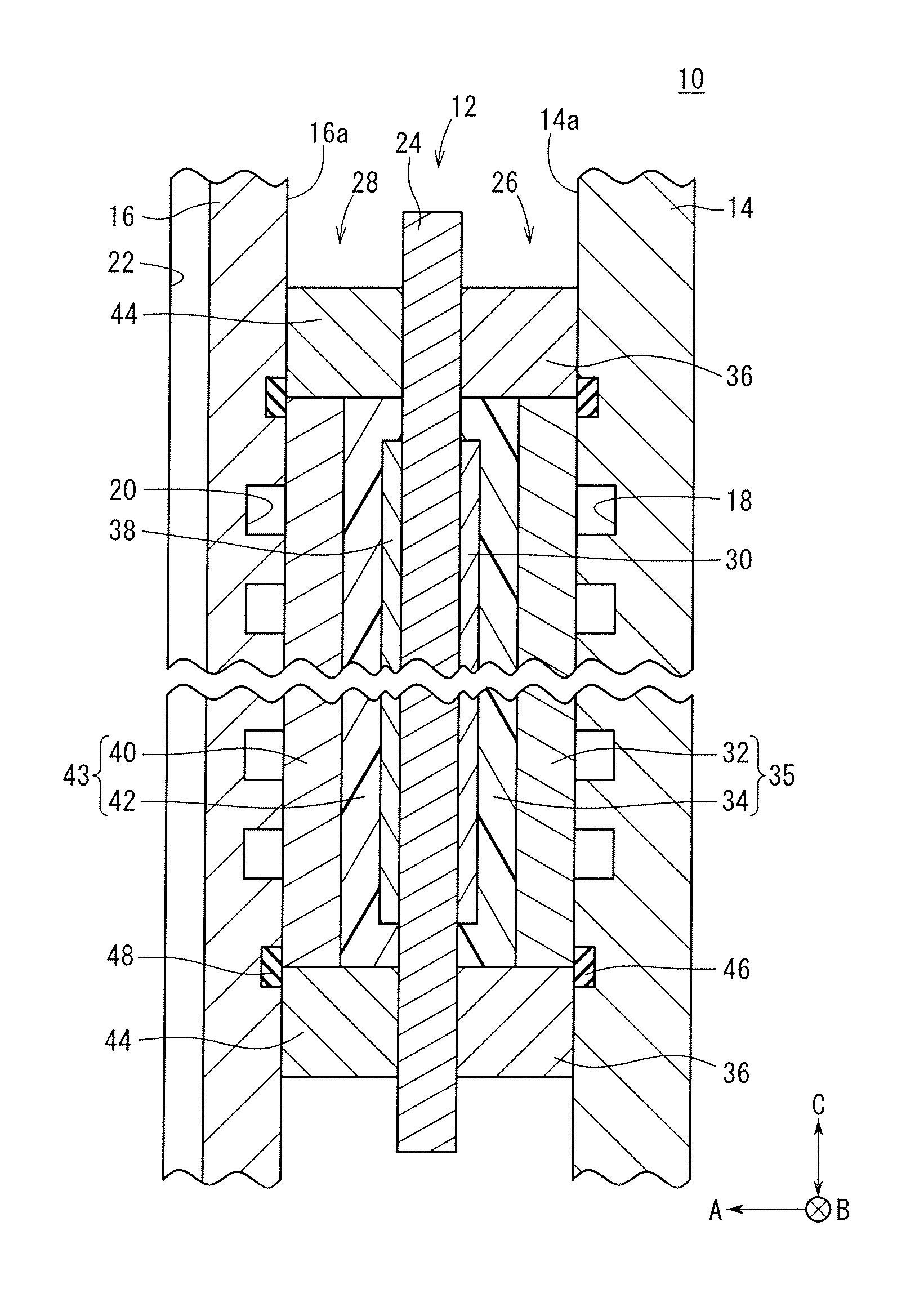
[0082](1) First and second gas diffusion layers having the same structure were formed in the same manner. Specifically, a carbon paper having a bulk density of 0.31 g / m2 and a thickness of 190 μm was impregnated with a dispersion liquid of a tetrafluoroethylene-hexafluoropropylene copolymer (FEP), FEP 120-JRB DISPERSION (trade name) available from Du Pont-Mitsui Fluorochemicals Co., Ltd., and the resultant paper was dried at 120° C. for 30 minutes. In this step, the dry weight ratio of the FEP to the carbon paper was 2.4% by weight.

[0083](2) 3 to 20 g of a vapor-grown carbon VGCF (trade name) available from Showa Denko K.K., 5 to 50 g of a dispersion liquid FEP 120-JRB (having a solid content concentration of 54%, trade name) available from Du Pont-Mitsui Fluorochemicals Co., Ltd., and 200 g of ethylene glycol were stirred and mixed using a ball mill to prepare a porous layer paste A.

[0084](3) The porous layer paste A prepared in (2) was applied by a blade coater to the first gas di...

example 2

[0091]In the step of (3), the porous layer paste A prepared in (2) was applied by the blade coater to the first gas diffusion layer formed in (1) in such a manner that the resultant first porous layer had a thickness of 30 μm. A membrane electrode assembly of Example 2 was produced in the same manner as Example 1 except for the step of (3).

example 3

[0092]In the step of (4), the porous layer paste A prepared in (2) was screen-printed as the ink on the second gas diffusion layer formed in (1) in such a manner that the resultant second porous layer had a thickness of 30 μm. A membrane electrode assembly of Example 3 was produced in the same manner as Example 1 except for the step of (4).


PUM

PropertyMeasurementUnit
Pressureaaaaaaaaaa
Pressureaaaaaaaaaa
Thicknessaaaaaaaaaa

Abstract

A membrane electrode assembly is prepared by sandwiching an electrolyte membrane between an anode and a cathode. In the anode, a first porous layer is interposed between a first electrode catalyst layer and a first gas diffusion layer. In the cathode, a second porous layer is interposed between a second electrode catalyst layer and a second gas diffusion layer. A first piled body of the first gas diffusion layer and the first porous layer has a percolation pressure higher than that of a second piled body containing the second gas diffusion layer and the second porous layer. The first piled body has a percolation pressure of 25 to 120 kPa, and the second piled body has a percolation pressure of 5 to 25 kPa.

Description

CROSS-REFERENCE TO RELATED APPLICATIONS[0001]This application is based upon and claims the benefit of priority from Japanese Patent Applications No. 2013-064901 filed on Mar. 26, 2013 and No. 2014-038054 filed on Feb. 28, 2014, the contents all of which are incorporated herein by reference.BACKGROUND OF THE INVENTION[0002]1. Field of the Invention[0003]The present invention relates to a membrane electrode assembly containing a solid polymer electrolyte membrane and electrodes disposed on either side thereof, wherein each of the electrodes contains an electrode catalyst layer, a gas diffusion layer, and a porous layer interposed between the electrode catalyst layer and the gas diffusion layer.[0004]2. Description of the Related Art[0005]In a solid polymer fuel cell, a membrane electrode assembly is interposed between a pair of separators to form a unit cell. The membrane electrode assembly contains an ion-exchange polymer electrolyte membrane, an anode facing one surface of the membr...

Claims


Application Information

Patent Timeline
IPC IPC(8): H01M8/10
CPCH01M8/1004H01M8/0234H01M8/0239Y02E60/50
Inventor FUKUMIZU, TAKAOMATSUMORI, HIROSHIASANO, YOICHIYAMAWAKI, TAKUMA
Owner HONDA MOTOR CO LTD
Why Eureka
Try Eureka