Eureka AIR delivers breakthrough ideas for toughest innovation challenges, trusted by R&D personnel around the world.

Solar tracker, sun tracking method, solar power generator, and controller

Active Publication Date: 2014-06-26
PANASONIC INTELLECTUAL PROPERTY MANAGEMENT CO LTD
View PDF9 Cites 5 Cited by
  • Summary
  • Abstract
  • Description
  • Claims
  • Application Information

AI Technical Summary

Benefits of technology

The present invention provides a solar tracker system that can efficiently track the sun and generate electric power. It uses a sensor to estimate the orientation of the solar tracker and correct any errors that may occur during installation. The invention can also be corrected using software, making it easier to adjust the solar position. This technology allows for more accurate tracking of the sun and improved efficiency in generating solar power.

Problems solved by technology

In that case, the power generating efficiency might decrease.
According to such a configuration for calculating the azimuth of the sun based on the date and time, however, if the orientation of the solar power generator itself was significantly different from its target orientation, it would be very difficult to correct the orientation.
In addition, in such a situation, even if the tracking error could be corrected successfully at a particular date and time so that the solar power generator can track the sun accurately, the error could rather increase at a different date and time.

Method used


Image

  • Solar tracker, sun tracking method, solar power generator, and controller
  • Solar tracker, sun tracking method, solar power generator, and controller
  • Solar tracker, sun tracking method, solar power generator, and controller

Examples


embodiment 1

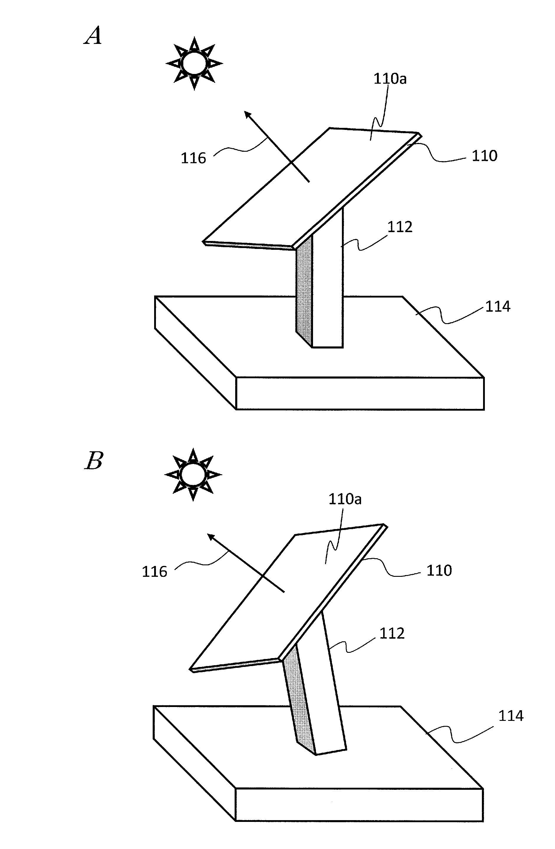
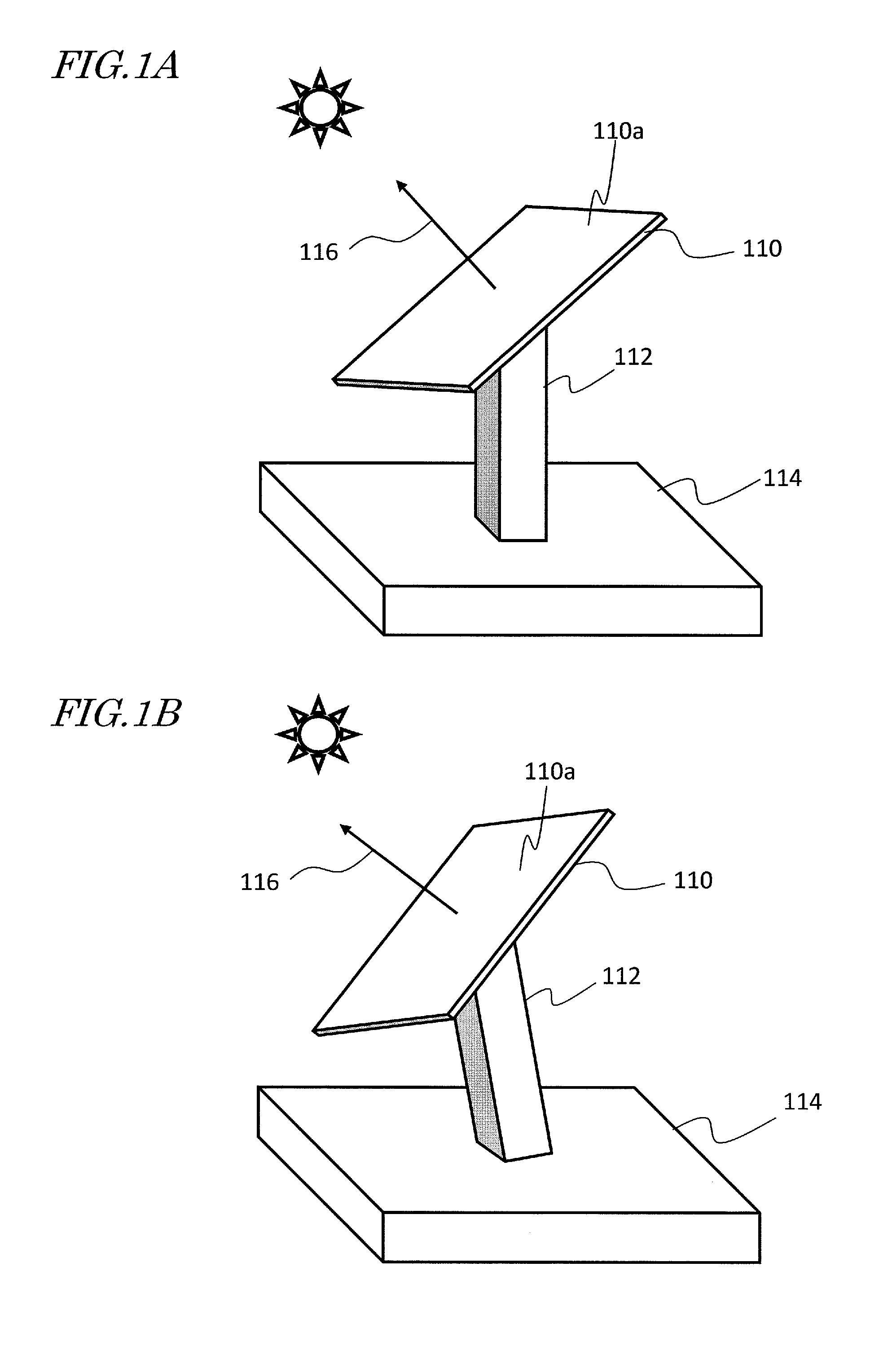
[0049]A solar tracker according to this embodiment has the configuration shown in FIG. 4. The solar tracker shown in FIG. 4 includes a supporting mechanism 112 which supports a solar panel 110 so as to be ready to change the orientation of the solar panel (110), a quantity of power generated measuring section 5 which measures the quantity of the electric power generated by the solar panel 110, a solar position getting section 6 which gets information [φ1, θ1] about the theoretical solar position at an arbitrary point in time, and a driving section 34 which changes the orientation of the solar panel 110 so that a normal to a solar collector plane 110a of the solar panel 110 tracks the sun.

[0050]The solar panel 110 has a configuration in which a plurality of concentrating photovoltaic generator modules are arranged two-dimensionally on its solar collector plane. Each of those photovoltaic generator modules includes a photovoltaic element which converts incoming sunlight into electric ...

embodiment 2

[0117]In the first embodiment described above, in estimating the attitude error Xt, the covariance matrix Rt of the measured value of the solar positional shift Yt is supposed to be set based on the external factor 10. However, the covariance matrix Rt of the measured value of the solar positional shift Yt may also be set by the operator of this device by him- or herself. The reason is that an operator should generally know the setup location very well and should be able to make a decision by all of his or her five senses at what timing the device needs to make a measurement to obtain a measured value with the highest degree of reliability.

[0118]FIG. 11 is a block diagram illustrating a configuration for this second embodiment. In the example shown in FIG. 11, instead of the external factor 10 given to the attitude error estimating section 12 shown in FIG. 4, an operating section 30 to be operated by the operator is connected. The operating section 30 may be a button or switch with ...

embodiment 3

[0129]A third embodiment of the present disclosure is characterized by the dither control section 7, which operates differently from its counterpart of the first and second embodiments described above. Specifically, according to the first and second embodiments described above, the range of the dither operation is supposed to be constant. However, if the range of the dither operation were more than necessarily broad, it would take a longer time to get the dither operation done and eventually estimate the attitude error Xt. On the other hand, according to this third embodiment, the dither operation can get done in a shorter time.

[0130]According to this embodiment, in the process of updating the estimated attitude error Xt, a covariance matrix Rt indicating its degree of reliability is obtained to find its degree of reliability. And the solar position measuring section predicts the solar positional shift and determines the range of the dither operation based on that degree of reliabil...


PUM


Abstract

A solar tracker comprises: a measuring section which measures the quantity of electric power generated by a solar panel; a solar position getting section which gets information about the theoretical solar position; a driving section which changes the orientation of the solar panel; a dither control section which measures a solar position; a positional shift measuring section which measures a solar positional shift between the measured solar position and the theoretical solar position. The driving section corrects the theoretical solar position based on the estimated attitude error and controls the orientation of the solar panel based on the theoretical position corrected.

Description

[0001]This is a continuation of International Application No. PCT / JP2013 / 003475, with an international filing date of Jun. 3, 2013, which claims priority of Japanese Patent Application No. 2012-281008, filed on Dec. 25, 2012, the contents of which are hereby incorporated by reference.BACKGROUND[0002]1. Technical Field[0003]The present application relates to a solar tracker and a sun tracking method, and more particularly relates to a solar tracker and sun tracking method which may be used in a solar power generator which generates electric power by making a solar panel concentrate incoming sunlight while tracking the sun. The present application further relates to a solar power generator including such a solar tracker and a controller and control program for use in such a solar tracker.[0004]2. Description of the Related Art[0005]A sun-tracking solar power generator is known as a kind of solar power generator, and includes a solar tracker which orients a single or multiple concentra...

Claims


Application Information

Patent Timeline
IPC IPC(8): H01L31/042G01S3/786
CPCF24S50/20G01S3/7861H02S20/32Y02B10/10Y02E10/47Y02E10/50H02S20/00
Inventor FUTAKUCHI, RYUTAROYAMAMOTO, MASAKI
Owner PANASONIC INTELLECTUAL PROPERTY MANAGEMENT CO LTD
Why Eureka
Eureka Blog
Learn More