Lithographic apparatus, computer program, device manufacturing method, and device manufactured thereby

Active Publication Date: 2005-08-30
ASML NETHERLANDS BV
View PDF5 Cites 7 Cited by
  • Summary
  • Abstract
  • Description
  • Claims
  • Application Information

AI Technical Summary

Benefits of technology

[0020]By storing the two relative positions an exposure position can be calculated easily. The table can then be moved directly to the exposure position when it is transferred from the first station to the second s

Problems solved by technology

This limits the throughput and also the

Method used


Image

  • Lithographic apparatus, computer program, device manufacturing method, and device manufactured thereby
  • Lithographic apparatus, computer program, device manufacturing method, and device manufactured thereby

Examples


Example

[0030]In the Figures, corresponding reference symbols indicate corresponding parts.

DETAILED DESCRIPTION

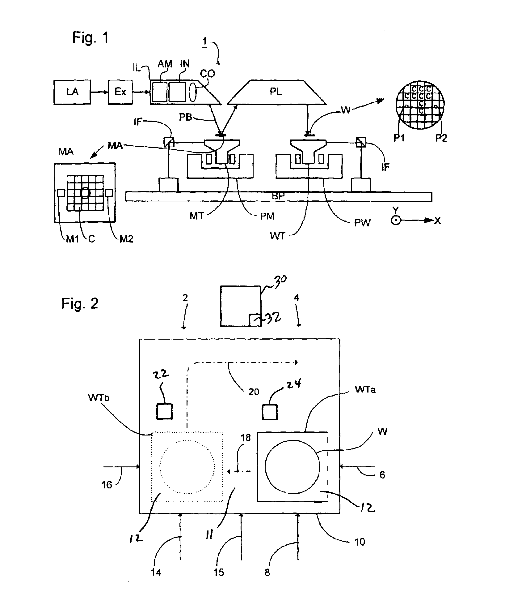
[0031]FIG. 1 schematically depicts a lithographic projection apparatus 1 according to an embodiment of the invention. The apparatus 1 includes a base plate BP. The apparatus may also include a radiation source LA (e.g. UV or EUV radiation, such as, for example, generated by an excimer laser operating at a wavelength of 248 nm, 193 nm or 157 nm, or by a laser-fired plasma source operating at 13.6 nm). A first object (mask) table MT is provided with a mask holder configured to hold a mask MA (e.g. a reticle), and is connected to a first positioning device PM that accurately positions the mask with respect to a projection system or lens PL. A second object (substrate) table WT is provided with a substrate holder configured to hold a substrate W (e.g. a resist-coated silicon wafer), and is connected to a second positioning device PW that accurately positions the substrate with respect ...


PUM


Abstract

A lithographic projection apparatus including an interferometer system having a reach extending over a first, measurement station and a second, exposure station. The apparatus stores the position of the mask relative to the mask table initially. A wafer table may be transferred from the first, measurement station to the second, exposure station while fully under the control of the interferometer system. The critical path through the exposure station may then be reduced. The apparatus stores the position of the wafer relative to the wafer table at the measurement station. Subsequent alignment in the exposure station may then be performed in a shorter time as the position of the mask relative to a mask table is known.

Description

RELATED APPLICATION[0001]This application claims the benefit of priority to European Patent Application No. 02256615.2, filed Sep. 24, 2002, the contents of which are herein incorporated by reference.BACKGROUND OF THE INVENTION[0002]1. Field of the Invention[0003]The present invention relates to a lithographic projection apparatus, a computer program, a device manufacturing method, and a device manufactured thereby.[0004]2. Description of the Related Art[0005]The term “patterning device” as here employed should be broadly interpreted as referring to device that can be used to endow an incoming radiation beam with a patterned cross-section, corresponding to a pattern that is to be created in a target portion of the substrate. The term “light valve” can also be used in this context. Generally, the pattern will correspond to a particular functional layer in a device being created in the target portion, such as an integrated circuit or other device (see below). An example of such a patt...

Claims


Application Information

Patent Timeline
IPC IPC(8): G03F7/20H01L21/027
CPCG03F7/70716G03F7/7075G03F7/70733G03F7/20
Inventor VAN DE NIEUWELAAR, NORBERTUS JOSEPHUS MARTINUS
Owner ASML NETHERLANDS BV
Why Eureka
Try Eureka