Method of forming organic light emitting pattern and apparatus for forming organic light emitting pattern of organic electro-luminescence display using sublimation type thermal transfer method

a technology of light emitting pattern and organic light, which is applied in the direction of electrical apparatus, photovoltaic energy generation, semiconductor devices, etc., can solve the problems of difficult application of deposition process to large area substrates, increased process time and process cost, and difficult to obtain fine patterns. , to achieve the effect of promoting an effective use of deposition material and quick and simplified process

Active Publication Date: 2014-10-02
SAMSUNG DISPLAY CO LTD
View PDF5 Cites 3 Cited by
  • Summary
  • Abstract
  • Description
  • Claims
  • Application Information

AI Technical Summary

Benefits of technology

[0053]Further, there is provided a rapid and simplified process of depositing an organic light emitting layer having durability.
[0054]Further, it is possible to promote an effective use of a deposition material.

Problems solved by technology

However, in the deposition process using the shadow mask, it is difficult to obtain a fine pattern and it is also difficult to apply the deposition process to a large area substrate due to a limitation of equipment.
Further, since the shadow mask should be frequently replaced, there are problems in that a process time and process cost are increased.
Further, since an interval between the substrate and a source should be increased to form a uniform thickness of the organic emission layer, there is a problem in that deposition using efficiency of a material forming the organic emission layer is reduced.
However, if localized heat is applied over a short period of time for a high resolution, it is difficult to deposit a high-quality organic layer due to a high sublimation ratio of the deposition material, and on the other hand, slow heating reduces the resolution.

Method used


Image

  • Method of forming organic light emitting pattern and apparatus for forming organic light emitting pattern of organic electro-luminescence display using sublimation type thermal transfer method
  • Method of forming organic light emitting pattern and apparatus for forming organic light emitting pattern of organic electro-luminescence display using sublimation type thermal transfer method
  • Method of forming organic light emitting pattern and apparatus for forming organic light emitting pattern of organic electro-luminescence display using sublimation type thermal transfer method

Examples


Embodiment Construction

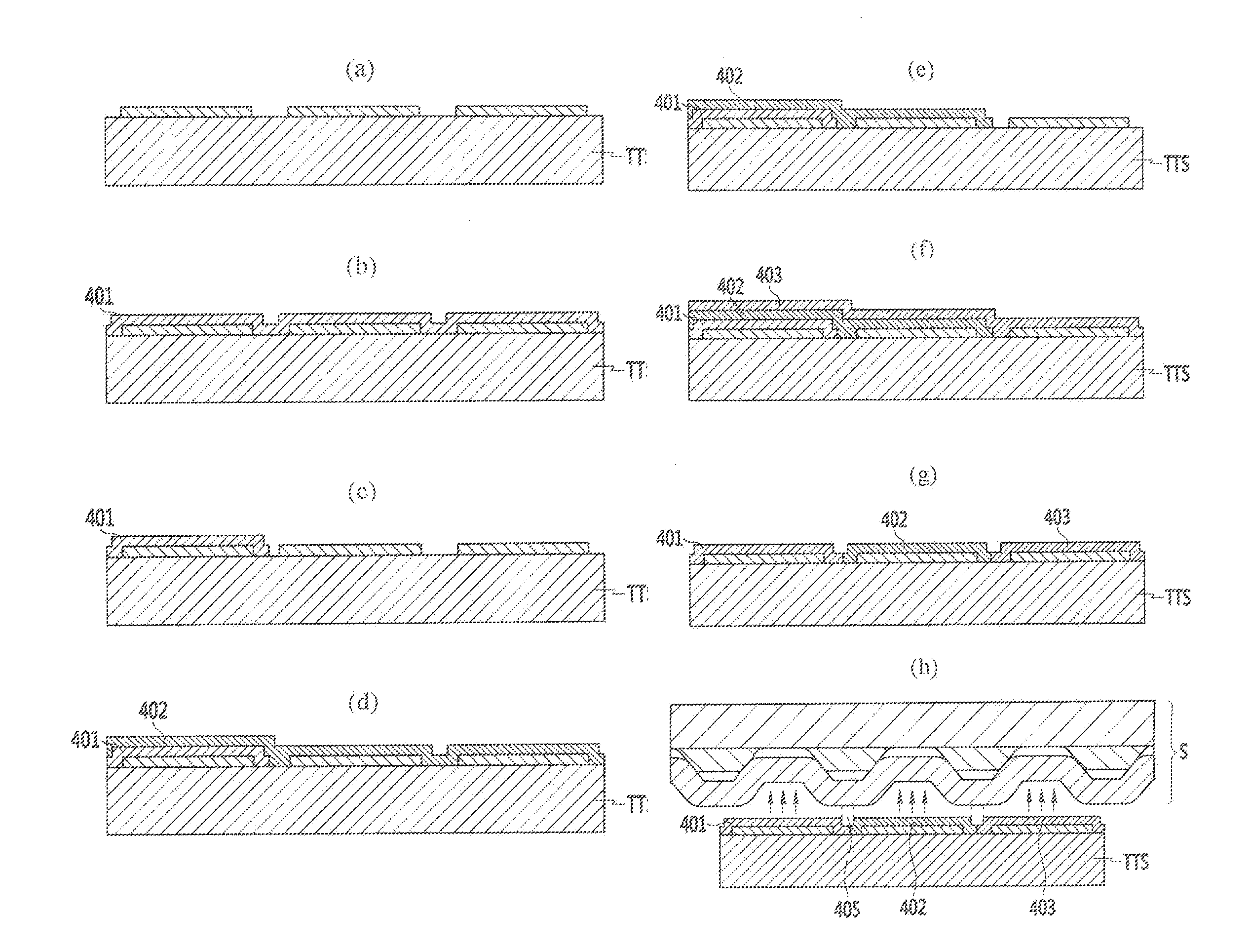
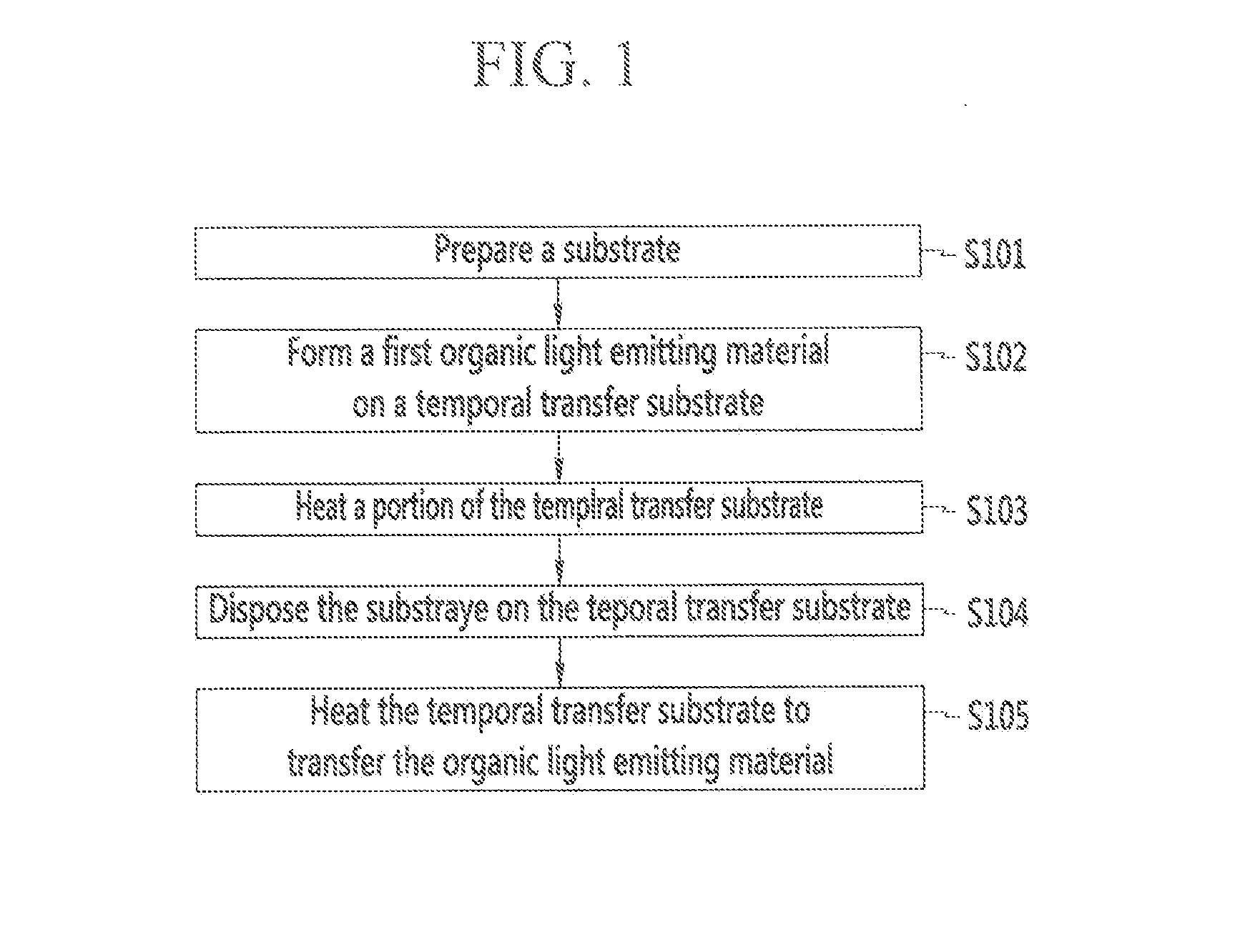
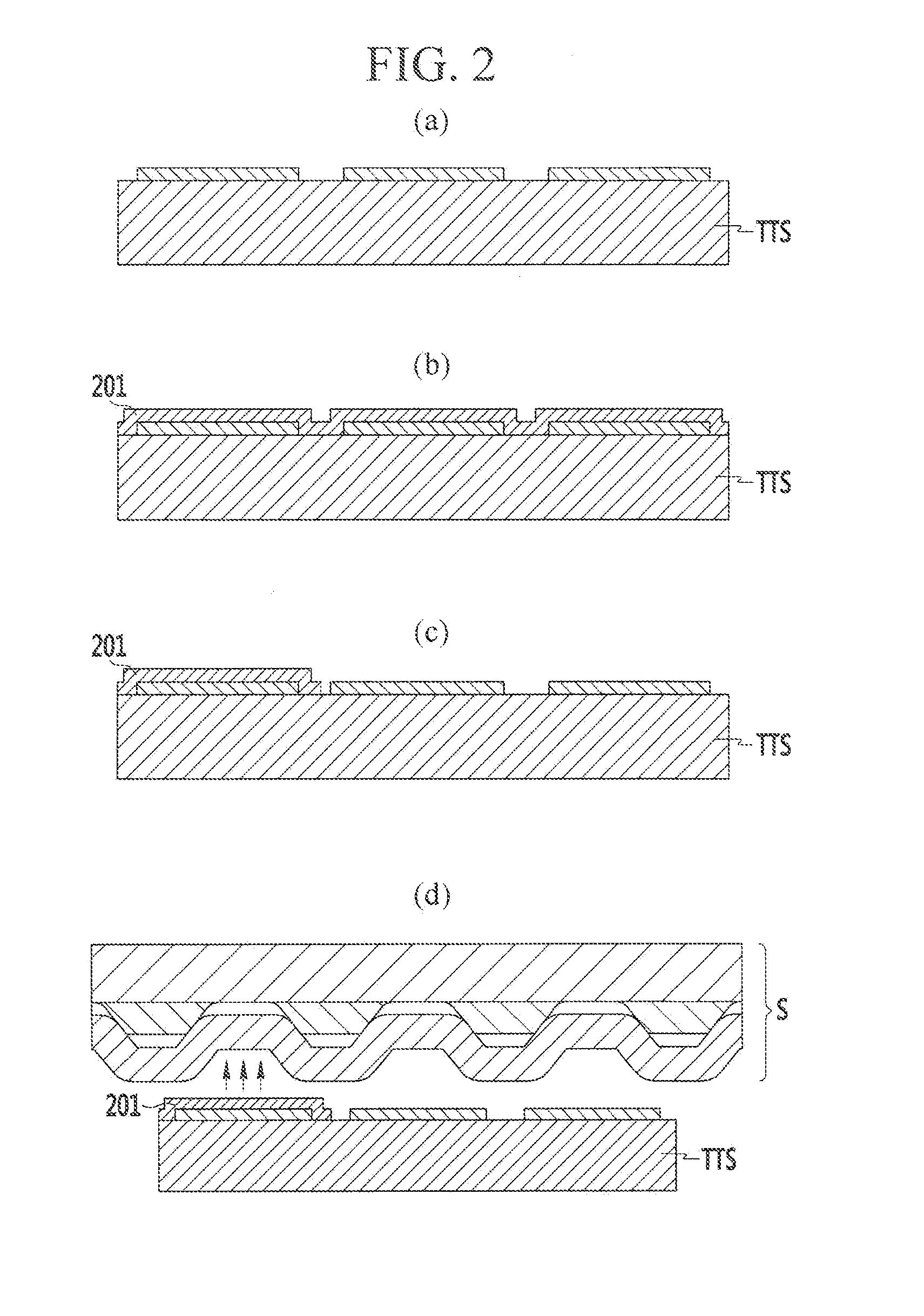
[0062]Hereinafter, exemplary embodiments of the present invention will be described more fully with reference to the accompanying drawings, in which exemplary embodiments of the invention are shown. As those skilled in the art would realize, the described embodiments may be modified in various different ways, all without departing from the spirit or scope of the present invention.

[0063]In addition, in various exemplary embodiments, the same reference numerals are used in respects to the constituent elements having the same constitution and illustrated in the first exemplary embodiment, and in the other exemplary embodiment, only constitution that is different from the first exemplary embodiment is illustrated.

[0064]It is described that the drawings are schematic and are not dimensionally illustrated. Relative dimensions and ratios of portions of the drawings are exaggerated or reduced in size for clarity and convenience, and a predetermined dimension is just illustrative but not lim...


PUM


Abstract

A method of forming an organic light emitting pattern of an organic electro-luminescence display according to an exemplary embodiment of the present invention includes preparing a display substrate in which a region where a first organic light emitting material is to be formed is defined, preparing a temporal transfer substrate (TTS) that is a transfer subject on which the first organic light emitting material is to be transferred, forming the first organic light emitting material on the temporal transfer substrate, applying heat to a portion other than a first region of the temporal transfer substrate to remove the first organic light emitting material formed on the portion other than the first region, disposing the temporal transfer substrate and the display substrate to closely face each other, and applying heat to the temporal transfer substrate to transfer the organic light emitting material on the display substrate.

Description

CLAIM OF PRIORITY[0001]This application claims priority to and the benefit of Korean Patent Application No. 10-2013-0033062 filed in the Korean Intellectual Property Office on Mar. 27, 2013, the entire contents of which are incorporated herein by reference.BACKGROUND OF THE INVENTION[0002]1. Field of the Invention[0003]The present description relates to a method of forming an organic light emitting pattern and an apparatus for forming the organic light emitting pattern of an organic electro-luminescence display, and more particularly, to a method of forming an organic light emitting pattern and an apparatus for forming the organic light emitting pattern using a sublimation type thermal transfer method.[0004]2. Description of the Related Art[0005]A current organic electro-luminescence display is a self-light emitting type and does not require a backlight unlike a liquid crystal display (LCD), and thus weight reduction and slimness thereof are feasible and the organic electro-luminesc...

Claims


Application Information

Patent Timeline
Patent Type & Authority Applications(United States)
IPC IPC(8): H01L51/00
CPCH01L51/0013Y02E10/549H10K71/18H10K77/10H10K50/80H10K50/00H10K2102/301H10K71/00
Inventor VORONOV, ALEXANDERHAN, GYOO-WAN
Owner SAMSUNG DISPLAY CO LTD
Why Eureka
Try Eureka