Connector

a technology of connecting rods and molded housings, applied in the direction of coupling device connections, coatings, coupling device details, etc., can solve the problems of difficult to correct variations, reduce yield, and increase the number of resin injection gates provided, so as to improve the moldability of the overmolded housing, the effect of simplifying the mold structur

Active Publication Date: 2014-10-02
YAZAKI CORP
View PDF7 Cites 6 Cited by
  • Summary
  • Abstract
  • Description
  • Claims
  • Application Information

AI Technical Summary

Benefits of technology

[0034]Moreover, in the case where the plurality of molded housings are formed in the structure integrated by the carrier portions and the overmolded housing is formed by molding, the plurality of molded housings may be mounted to the mold of the overmolded housing by a single operation, thereby enhancing the moldability of the overmolded housing.
[0035]In addition, according to the configuration of (2), since the dimensions of the carrier portions in the direction orthogonal to the direction in which the molded housings are lined up are significantly smaller than the dimensions of the molded housing in the same direction, ensuring flexibility in the direction orthogonal to the direction in which the molded housings are lined up is facilitated. Therefore, even though variations in the arrangement pitch between the adjacent molded housings occur due to the effects of shrinkage and warpage that occur in the carrier portions during molding, it is possible to correct the variations in the arrangement

Problems solved by technology

However, in this configuration, the plate thickness of the carrier portion that joins the plurality of the molded housings 140 to one another is increased, and thus variations in the arrangement pitch between the adjacent molded housings 140 are likely to occur due to the effects of shrinkage and warpage that occur in the carrier portion during molding.
Moreover, since the carrier portion ha

Method used


Image

  • Connector
  • Connector
  • Connector

Examples


Embodiment Construction

[0050]Hereinafter, exemplary embodiments of a connector according to the present invention will be described in detail with reference to the drawings.

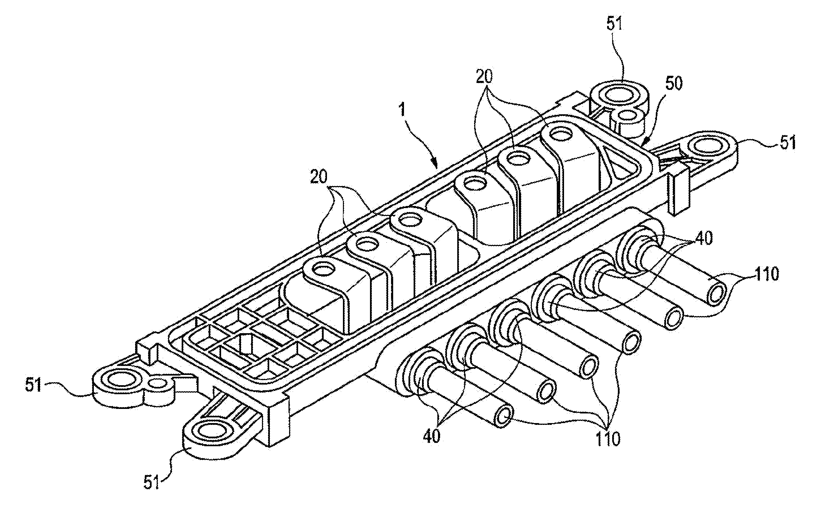
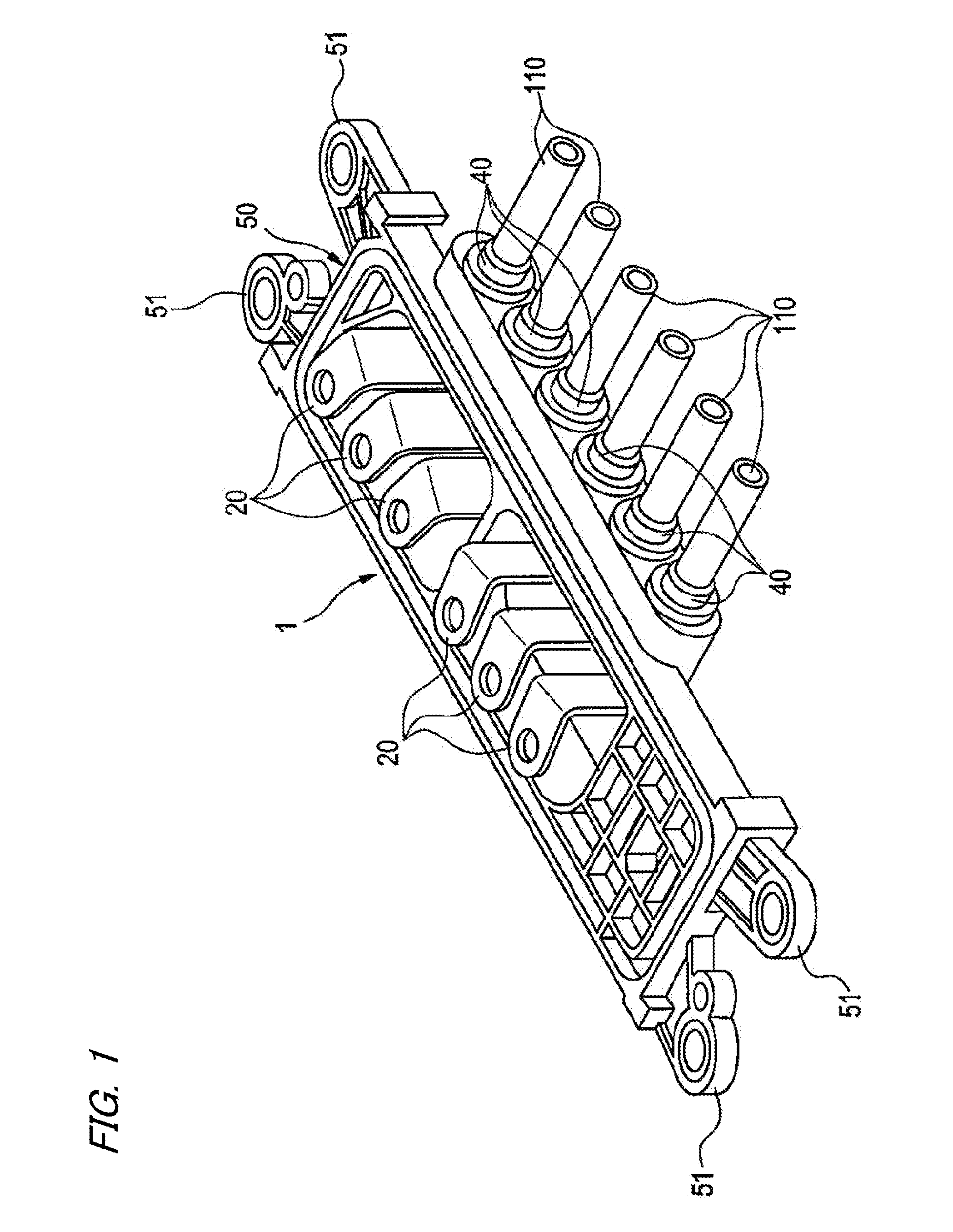
[0051]FIGS. 1 to 4 illustrate an embodiment of the connector according to the present invention. FIG. 1 is a perspective view of an assembled state of the connector of the embodiment of the present invention. FIG. 2 is a perspective view of a plurality of metal terminal fittings accommodated at predetermined pitches in the connector of FIG. 1. FIG. 3 is a perspective view of a state in which the plurality of metal terminal fittings illustrated in FIG. 2 are integrated by molding molded housings and carrier portions. FIG. 4 is an enlarged plan view illustrating a state in which a plurality of the molded housings illustrated in FIG. 3 are integrated by the carrier portions.

[0052]The connector 1 of the embodiment includes a plurality of electric wires 110 having insulation coatings on the outer peripheries, a plurality of the metal termin...


PUM

PropertyMeasurementUnit
Flexibilityaaaaaaaaaa
Dimensionaaaaaaaaaa

Abstract

A connector includes a plurality of metal terminal fittings connected to terminals of electric wires, a plurality of molded housings molded to connection parts of the electric wires and the metal terminal fittings to cover the connection parts, and an overmolded housing which accommodates and holds the plurality of molded housings. The plurality of molded housings are molded in a structure integrated by carrier portions that connect the adjacent molded housings to each other and are collectively integrated into the overmolded housing. The carrier portions have cross-section dimensions set to be smaller than those of the molded housing and have flexibility. An arrangement pitch between the adjacent molded housings are adjusted when the plurality of molded housings are collectively integrated into the overmolded housing.

Description

CROSS REFERENCE TO RELATED APPLICATIONS[0001]This application is a continuation of PCT application No. PCT / JP2012 / 084282, which was filed on Dec. 26, 2012 based on Japanese Patent Application No. 2011-286391, filed on Dec. 27, 2011, the contents of which are incorporated herein by reference.BACKGROUND OF THE INVENTION[0002]1. Field of the Invention[0003]The present invention relates to a connector having a structure in which a plurality of molded housings molded to connection parts of electric wires and metal terminal fittings are accommodated and held in an overmolded housing.[0004]2. Description of the Related Art[0005]FIG. 7 illustrates a connector disclosed in PTL 1 below.[0006]The connector 100 includes a metal terminal fitting 120 connected to the terminal of an electric wire 110, a molded housing 140 which is molded to a connection part 130 between the electric wire 110 and the metal terminal fitting 120 to cover the connection part 130, and an overmolded housing 150 which ac...

Claims


Application Information

Patent Timeline
IPC IPC(8): H01R13/516
CPCH01R13/516H01R13/405H01R13/514H01R43/18H01R43/24B29C45/14467B29C45/14639B29C45/1671B29C45/2708B29C45/0046
Inventor TANAKA, MASAHIROKATO, HAJIMEOHISHI, MADOKAKATO, SOTAROMIYAJIMA, TAKAAKI
Owner YAZAKI CORP
Why Eureka
Try Eureka