Laryngoscope and laryngoscope blades

a technology of laryngoscope and blade, which is applied in the field of laryngoscope and video laryngoscope, can solve the problems of time-consuming and laborious blade change, inability to choose the blade type, and weight loss, and achieve the effect of improving the view of the screen

Inactive Publication Date: 2014-10-02
COVIDIEN AG
View PDF1 Cites 16 Cited by
  • Summary
  • Abstract
  • Description
  • Claims
  • Application Information

AI Technical Summary

Benefits of technology

[0018]The provision of a laryngoscope body having a blade retaining member that can be moved between (and typically fixed at) a plurality of orientations relative to the handle allows the blade retaining member to be oriented at a greater interior angle relative to the handle when using a blade having greater curvature whilst allowing the distal tip of a blade of greater curvature to be sufficiently far from the chest of the patient that intubation can proceed without the handle of the laryngoscope contacting the patient's chest. Therefore, the intubation procedure may be carried out faster or more efficiently than if the laryngoscope itself was required to be changed, and allows the medical practitioner carrying out the procedure to adjust the angle of the blade retaining member as needed.
[0127]Therefore, the ability to adjust the position of the blade retaining member from a first position to a second position, whilst the blade mounted onto the blade retaining member is inserted into a patient's oral cavity allows the intubation procedure to be carried out much more efficiently and with a lower equipment cost than is possible with laryngoscopes in the art.

Problems solved by technology

However, where there are anomalies within the oral cavity of the patient, or where an effective view of the larynx cannot be achieved with a direct view blade, for example, it is often necessary to use a blade with a greater curvature to allow the blade to be inserted into the oral cavity around any obstructions.
Changing blades can be time consuming and the desired blade type may not be available.
For example, when an indirect view blade is introduced into a patient there can be problems with the handle of the laryngoscope contacting the patient's chest.
Thus, whereas it is possible to produce robust blades, strength may be at the expense of weight and blade dimensions may require to be larger than optimal.
Whereas it has been possible to produce comparatively slimline blades, this has been at the expense of rigidity, durability or suitability for certain procedures and it is known for disposable laryngoscope blades to be either prone to cracking during use, requiring replacement of the disposable portion, or worse resulting in injury or increased risk of infection, or to be sufficiently large as to be difficult to work with.
Furthermore, if the blade bends too much under excessive force, the view of the larynx may be compromised.
However, it is not apparent how such a device could be used with both direct and indirect view blades as if the elongate member was oriented at the correct angle for a direct view blade, one would anticipate that a more curved indirect view blade fitted onto the same elongate member would have its tip in the wrong place.

Method used


Image

  • Laryngoscope and laryngoscope blades
  • Laryngoscope and laryngoscope blades
  • Laryngoscope and laryngoscope blades

Examples


Embodiment Construction

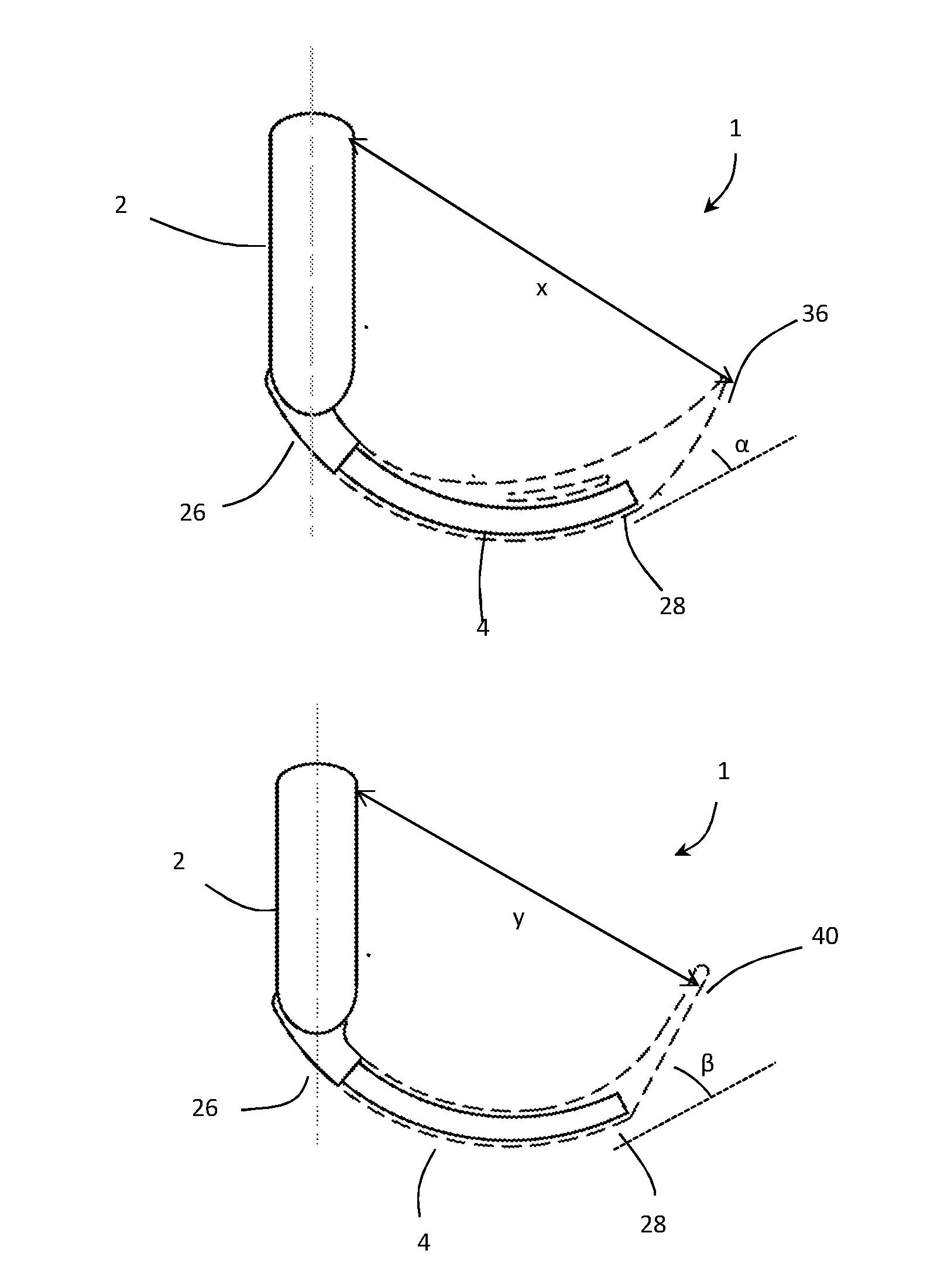
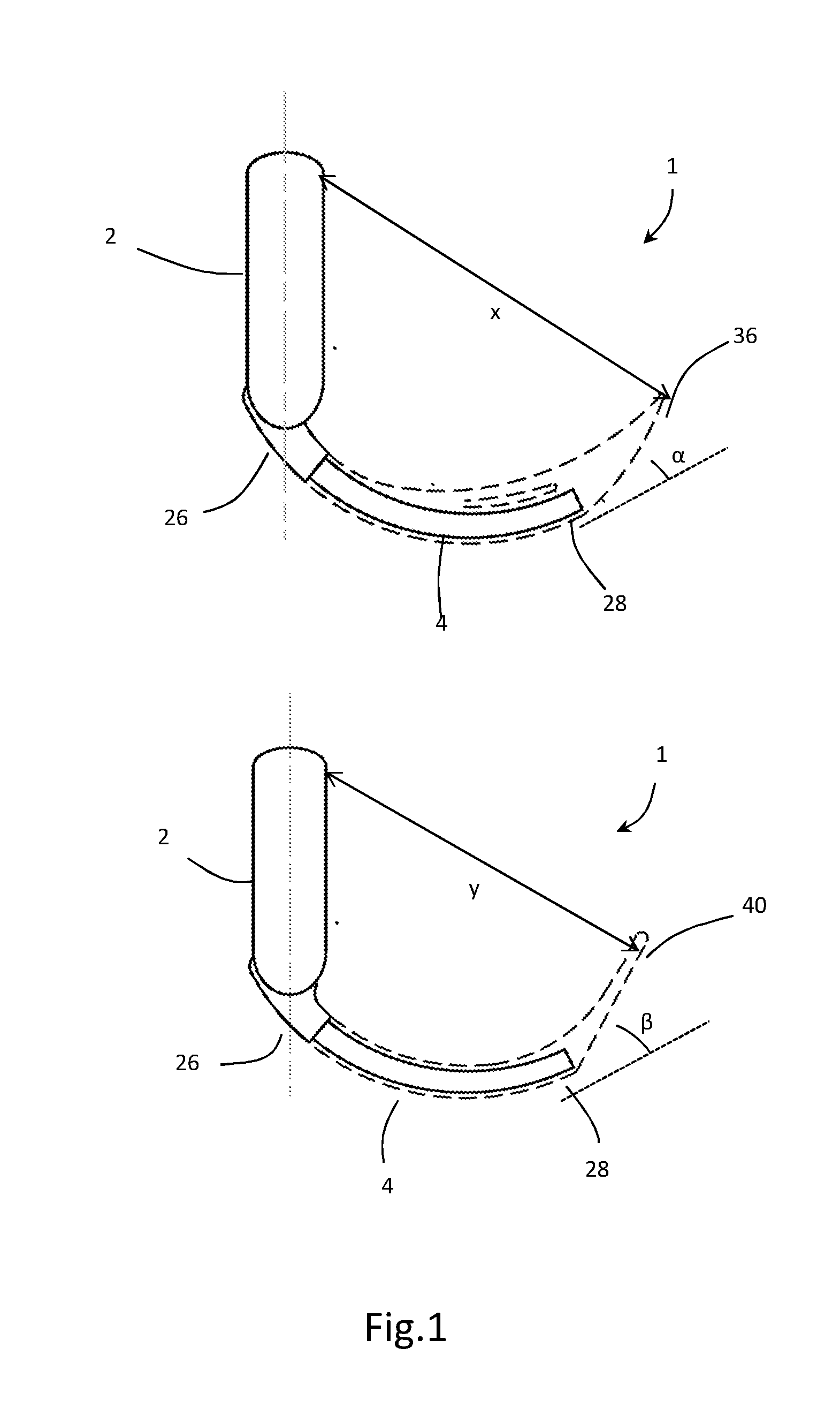
[0141]With reference to FIGS. 1 to 11 a laryngoscope body 1 comprises a handle 2 (functioning as the elongate handle) and a blade retaining member 4 pivotally mounted to the handle. The handle has a first end 6 and a second end 8 and comprises a display screen 10 adjacent to the first end (acting as a display screen assembly), an adjuster 12 adjacent to the second end, and a battery 14.

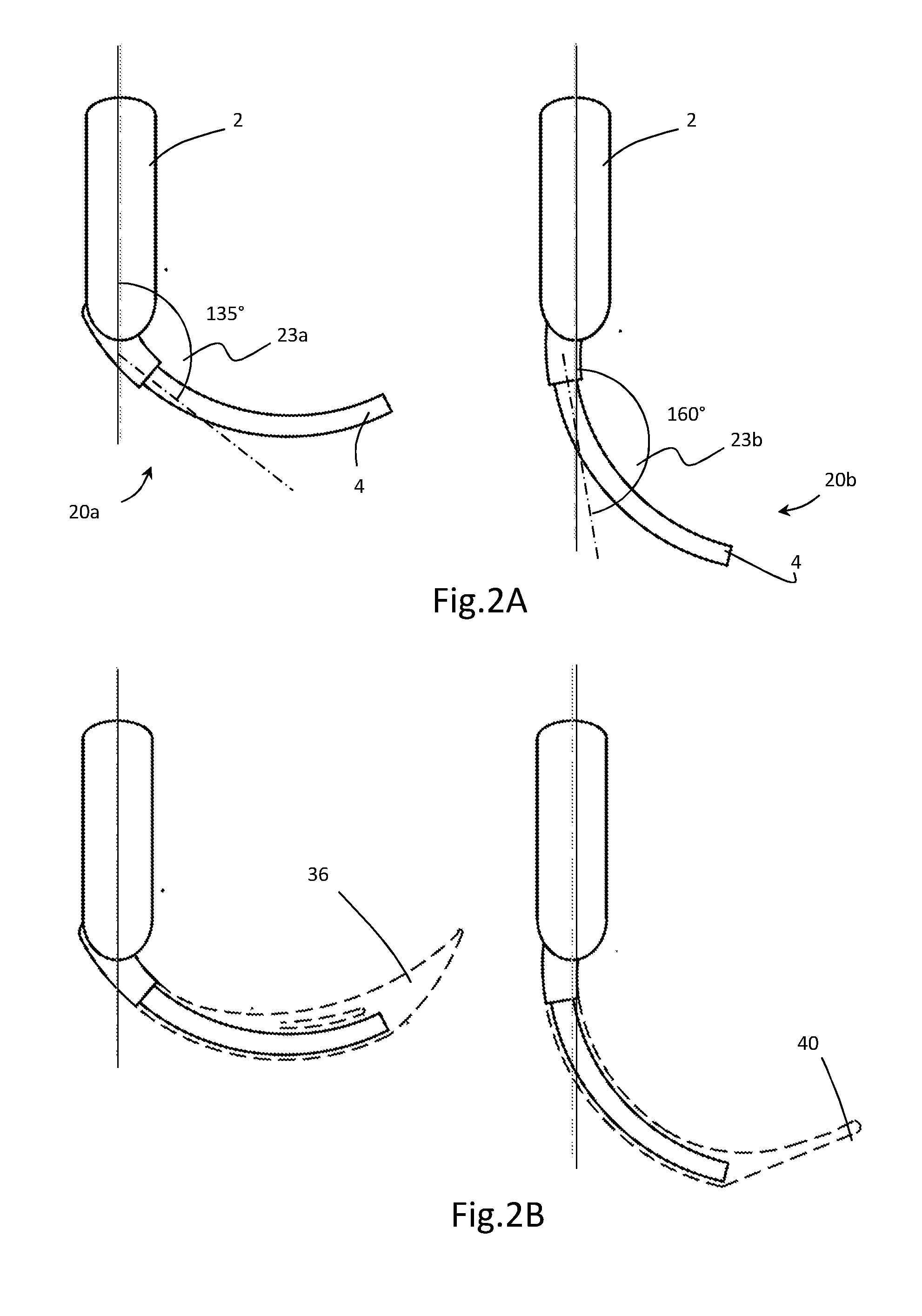
[0142]The adjuster comprises a release button 16, four guides (not shown) that define two discrete positions 20a, 20b in which the blade retaining member can be fixed, a position 21 in which the blade retaining member cannot be fixed and a storage position 22 where blade retaining member can be fixed, and a spring (acting as a resilient element). In the first position, the blade retaining member is fixed at an exit angle of 135°relative to the handle. In the second position, the blade retaining member is fixed at an exit angle of 160°relative to the handle. The blade retaining member can also be pivot...


PUM


Abstract

A laryngoscope body for use with laryngoscope blades is presented having an elongate handle and a blade retaining member configured to retain a blade such that the blade extends away from the elongate handle; wherein the blade retaining member is fixable at a plurality of positions to allow a blade to be retained on the blade retaining member at a plurality of—angles relative to the elongate handle. There is also disclosed a kit of parts comprising a laryngoscope body and a plurality of blades, as well as a method of use for the said laryngoscope body with a suitable laryngoscope blade.

Description

FIELD OF THE INVENTION[0001]The invention relates to the field of laryngoscopes and video laryngoscopes. Some embodiments of the invention relate to video laryngoscopes including an elongate blade retaining member comprising a video camera and configured to slidably receive a removable blade having a cooperating channel in use.BACKGROUND TO THE INVENTION[0002]Laryngoscopes are medical devices in common use in oral and tracheal medical procedures, and may be used to obtain view of the glottis or larynx, or to manipulate the tongue, glottis or larynx in order to facilitate insertion of endotracheal tubes or other instruments such as endoscopes, which may be separate pieces of equipment, or may be integral to a laryngoscope.[0003]A laryngoscope typically comprises a body and a blade, which is an elongate section which extends towards and into a patient's oral cavity during a medical procedure such as intubation. A laryngoscope blade may be integrally formed with the body, or demountabl...

Claims


Application Information

Patent Timeline
Patent Type & Authority Applications(United States)
IPC IPC(8): A61B1/267A61B19/00
CPCA61B1/00101A61B19/44A61B1/267A61B1/00147A61B90/90
Inventor MCGRATH, MATTHEW JOHN ROSSINGLIS, PETER DOUGLAS COLINRHODES, THOMAS JAMES
Owner COVIDIEN AG
Why Eureka
Try Eureka